Advertisement
Quick Links
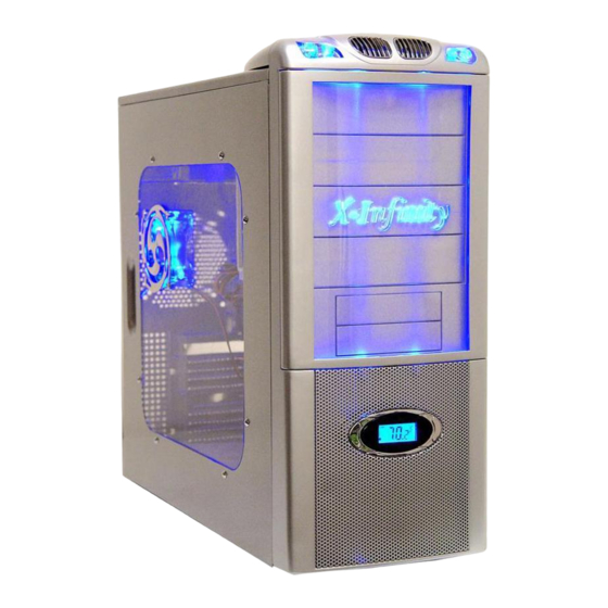
ATXB6KLW(X-Infinity) Series Installation Guide
1:Unscrew the thumb screws
from Side Panel.
4:Put the motherboard stand-offs 5.Sit the motherboard on the
on the motherboard tray.
7.Screw in all the screws into the
motherboard stand-offs
2.Pull the side panel back then
pull out.
motherboard tray.
8.Same as Step 7.
3:Find the motherboard stand-offs
from the enclosed screw box.
6.Find screws in the screw box.
Advertisement

Subscribe to Our Youtube Channel
Related Manuals for Apevia X-Infinity ATXB6KLW Series


Summary of Contents for Apevia X-Infinity ATXB6KLW Series
- Page 1 ATXB6KLW(X-Infinity) Series Installation Guide 1:Unscrew the thumb screws from Side Panel. 4:Put the motherboard stand-offs 5.Sit the motherboard on the on the motherboard tray. 7.Screw in all the screws into the motherboard stand-offs 2.Pull the side panel back then pull out. motherboard tray.
- Page 2 9.Take out front panel: (Optional. Only if you need to install front fans or replace LCD) Step (1): Unscrew the side panel panel (motherboard side) Step (4): Unscrew the other 2 screws from the other side. 11.Put the front panel back and screw to secure.
- Page 3 14.Screw all 5.25” drives in place. 17.Secure external 3.5” drives with screws in place. 20.Find the 20-pin connector from Power Supply. 15.3.5” External Drives: Force out 3.5” metal plate and drive cover with a screw driver. 18.3.5” Internal Drives: Install 3.5”...
- Page 4 23.Plug into your motherboard. (For Intel P4 motherboard only) 26.Find “HDD LED” and “Reset SW” cables. 29.Find “Case Speaker” from screw box. 24.Find 2*USB Cables.(USB1 & USB2) 27.Plug them onto your M/B. Please refer to M/B user manual. 30.Install case speaker onto M/B following M/B user manual.
- Page 5 32.Bring Audio Cables through the I/O slot and leave them outside of the case. 35.Install LED Lights: Find 2* LED connectors from the front Panel. 37.LCD Temperature Readout: Connect 4-pin Male connector from LCD to a 4-pin Female connector from power supply.
- Page 6 40.You can either tape the sensor on hard drive or on CPU Heat sink or leave it inside the case to get the overall system temperature. like after power on. 42.Real Fan (Optional): You can install 1*80mm up to 120mm at rear. Note: 1.You can link together all the 4-pin connectors(male to female) from all the case fans, LCD, LED, HDD just use one of the 4-pin Molex connectors from power supply.
Need help?
Do you have a question about the X-Infinity ATXB6KLW Series and is the answer not in the manual?
Questions and answers