Advertisement
Quick Links
(All screws for M/B, DVD, HDD and case keys are provided in a
screw box that comes with the case)
1.
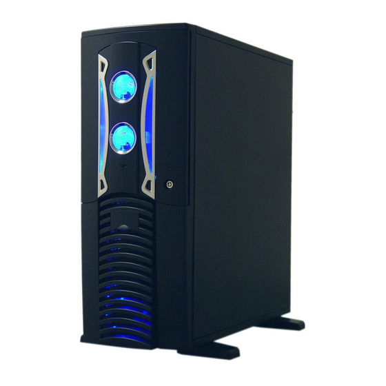
Install motherboard, 3.5" and 5.25" drives
1.1 Remove two thumb
screws from the back
of the side window
Finish look after installation.
1.2 Push the handle
towards front panel
a little bit, then pull
it out.
:
1.3 Make sure your
motherboard is
compatible with
the I/O panel, if
not, then push it
in to remove it.
Advertisement

Subscribe to Our Youtube Channel
Related Manuals for Apevia X-Pleasure


Summary of Contents for Apevia X-Pleasure
- Page 1 (All screws for M/B, DVD, HDD and case keys are provided in a screw box that comes with the case) Install motherboard, 3.5" and 5.25" drives 1.1 Remove two thumb screws from the back of the side window Finish look after installation. 1.2 Push the handle towards front panel a little bit, then pull...
- Page 2 1.4 Install I/O panel that comes with M/B. Most motherboards come with its own I/O panel. If your M/B does not come with it, then it is likely that you can use the one that already in the case. 1.7 Remove the 5.25 bay "...
- Page 3 1.10 Tighten screw drive rails on both sides of 5.25 drives " 1.13 Break and remove the 3.5 drive metal " plates 1.11 Slide the 5.25 drive " into the drive bay. Do the same for the rest 5.25 drives "...
-
Page 4: Identify Power Supply Connectors
1.17 Install internal 3.5 " 1.18 Put the drive cage 1.16 Remove 2nd 3.5 " drives such as HDD, back. drive cage for Serial ATA drives internal drives. and zip drives. 2.Identify power supply connectors: 4pin SATA Floppy Peripheral... - Page 5 20pin or 24pin Main Connector Your Power supply may have a 20pin or a 24pin or a 20+4pin main connector . If you have the 20+4 pin main connector, just detach the 4 pin to make it a 20 pin connector if your M/B only takes 20 pin.
- Page 6 3.4 Find these connectors from front panel: Power SW , Reset SW , HDD LED, Power LED and Speaker. 3.7 Refer to M/B use manual, plug USB and Firewire cables to M/B. 3.5 Refer to your M/B manual and plug these connectors to your M/B.
-
Page 7: Install Controller
4.Install front temp. sensor, fan connectors, fan speed controller: 4.1 Find temperature sensor from front panel. Note: You may also leave the sensor loose in the air inside your system to get an overall system's temperature as you wish. Please do not place the sensor on the CPU since it may melt the sensor. - Page 8 4.4 Daisy chain all 4 case fans first. Now you have two ends, one male and one female. 4.5 Then find 4pin connectors from front panel: INPUT " DC 12V (for fan " connection) and " OUTPUT 0.23A 5 FAN MAX 1.2A "...
- Page 9 USB cable pin assignment Firewire cable pin assignment...
Need help?
Do you have a question about the X-Pleasure and is the answer not in the manual?
Questions and answers