Advertisement
Table of Contents
- 1 Unscrew the Thumb Screws and Remove Side Panel
- 2 Take out Front Panel and Install Case Fans
- 3 Install Drives and Audio Cable Setup
- 4 Connect Power and USB Cables to Motherboard
- 5 Connect Front Panel Cables, Install Case Speaker, LED Lights, and LCD Temperature Readout
- 6 Sensor Placement, Case Feet Installation, and Notes on Connector Linking
- Download this manual
ATXB4KLW(X-Dreamer II) Series Installation Guide
1:Unscrew the thumb screws
from side panel.
4:Put the motherboard stand-offs 5.Sit the motherboard on the
on the motherboard tray.
7.Screw in all the screws into the
motherboard stand-offs
2.Pull the side panel back then
pull out.
motherboard tray.
8.Same as Step 7.
3:Find the motherboard stand-offs
from the enclosed screw box.
6.Find screws in the screw box.
Advertisement
Table of Contents

Related Manuals for Apevia X-Dreamer II ATXB4KLW Series


Summary of Contents for Apevia X-Dreamer II ATXB4KLW Series
- Page 1 ATXB4KLW(X-Dreamer II) Series Installation Guide 1:Unscrew the thumb screws from side panel. 4:Put the motherboard stand-offs 5.Sit the motherboard on the on the motherboard tray. 7.Screw in all the screws into the motherboard stand-offs 2.Pull the side panel back then pull out.
- Page 2 Step (1): Unscrew the side panel (motherboard side) Step (4): Unscrew the other 2 screws from the other side. 10.Optional:Install case fan in the front panel (You can put up to 2*80mm fans in the front.) Step (2): Take out the side panel (motherboard side) Step (5): Pull out the front panel from the bottom.
- Page 3 13.Secure the 5.25” drives in place with screws. 16.Screw all 3.5” hidden drives in place with screws. 19.Find the audio cables and bring them through the I/O slot to outside of the back panel. 14.Slide in 3.5” FDD Drive and secure with screws.
- Page 4 22.Find the 4pin connectors (Female and Male) from case Fan. Connect the Male to the Female 4pin from power supply. 25.Find the 4-pin P4 connector from power supply.(for P4 only) 28.Plug USB cables to your M/B. Please refer to M/B user manual. 23.Find the 20-pin connector from power supply.
- Page 5 31.Find “Power SW”, “+P LED” & “-P LED” cables and plug onto M/B. Please refer to M/B user manual. 35.Install LED Lights: Find 2*LED connectors from the front panel. They are 2*2-pin connectors that lead to 2*4-pin connectors (1*Male, 1*Female) 37.LCD Temperature Readout: Connect 4-pin Male connector from LCD to a 4-pin Female connector...
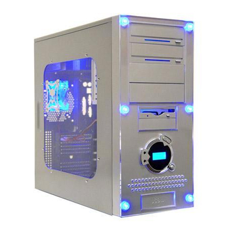
- Page 6 40.You can either tape the sensor on Hard Drive or on CPU Heat 41.This is how the case front panel sink or leave it inside the case to get the overall system temperature. looks like after powered on. 42.Find “Case Feet” in screw box. Lay case down and put “Case Feet”...
Need help?
Do you have a question about the X-Dreamer II ATXB4KLW Series and is the answer not in the manual?
Questions and answers