Table of Contents
Advertisement
Quick Links
Advertisement
Table of Contents

Related Manuals for Pepperl+Fuchs LVL-M3


Summary of Contents for Pepperl+Fuchs LVL-M3
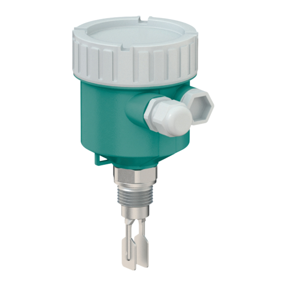
- Page 1 LVL-M3 Vibration Limit Switch Brief Instructions ISO9001...
- Page 2 Phone: +49 621 776 - 0 E-mail: info@de.pepperl-fuchs.com North American Headquarters Pepperl+Fuchs Inc. 1600 Enterprise Parkway Twinsburg, Ohio 44087 Phone: +1 330 425-3555 E-mail: sales@us.pepperl-fuchs.com Asia Headquarters Pepperl+Fuchs Pte. Ltd. P+F Building 18 Ayer Rajah Crescent Singapore 139942 Phone: +65 6779-9091 E-mail: sales@sg.pepperl-fuchs.com https://www.pepperl-fuchs.com...
-
Page 3: Table Of Contents
Vibration Limit Switch LVL-M3 Contents Introduction ............5 Content of this Document . - Page 4 Vibration Limit Switch LVL-M3 Contents...
-
Page 5: Introduction
Vibration Limit Switch LVL-M3 Introduction Introduction Content of this Document This document contains information that you need in order to use your product throughout the applicable stages of the product life cycle. These can include the following: • Product identification •... -
Page 6: Safety Information
Vibration Limit Switch LVL-M3 Introduction Safety Information Target Group, Personnel Responsibility for planning, assembly, commissioning, operation, maintenance, and dismounting lies with the plant operator. Only appropriately trained and qualified personnel may carry out mounting, installation, commissioning, operation, maintenance, and dismounting of the product. The personnel must have read and understood the instruction manual and the further documentation. - Page 7 Vibration Limit Switch LVL-M3 Introduction Informative Symbols Note This symbol brings important information to your attention. Action This symbol indicates a paragraph with instructions. You are prompted to perform an action or a sequence of actions. ▶ Reference to another section or to further documentation Permitted Procedures, processes or actions that are permitted.
-
Page 8: Basic Safety Instructions
Vibration Limit Switch LVL-M3 Basic Safety Instructions Basic Safety Instructions Requirements for Personnel The personnel must fulfill the following requirements to carry out the necessary tasks, e. g. commissioning and maintenance: • Trained, qualified specialists must have a relevant qualification for the specific function •... -
Page 9: Operational Safety
The device meets general safety standards and legal requirements. It also complies with the EU directives listed in the device-specific EU Declaration of Conformity. Pepperl+Fuchs confirms this by affixing the CE mark to the device. -
Page 10: Incoming Acceptance And Product Identification
Vibration Limit Switch LVL-M3 Incoming Acceptance and Product Identification Incoming Acceptance and Product Identification Incoming Acceptance Check the following during goods acceptance: □ Are the order codes on the delivery note and the product sticker identical? □ Are the goods undamaged? □... -
Page 11: Storage And Transport
Vibration Limit Switch LVL-M3 Incoming Acceptance and Product Identification Storage and Transport 3.3.1 Storage Conditions Use original packaging. 3.3.2 Storage Temperature -40 to +80 °C (-40 to +176 °F) 3.3.3 Device Transport Transporting the Device Transport the device to the measuring point in the original packaging. -
Page 12: Mounting
Vibration Limit Switch LVL-M3 Mounting Mounting Warning! Loss of protection rating if the device is opened in a wet environment. Only open the device in a dry environment! Mounting Instructions • Any orientation for device with short pipe up to approx. 500 mm (19.7 inch) •... -
Page 13: Mounting Requirements
Vibration Limit Switch LVL-M3 Mounting Mounting Requirements 4.1.1 Take Switch Point into Consideration The following are typical switch points, depending on the orientation of the device: water +23 °C (+73 °F) Note Minimum distance between the fork tip and the tank wall or pipe wall: 10 mm (0.39 inch) Figure 4.2... - Page 14 Vibration Limit Switch LVL-M3 Mounting High Viscosity Note Highly viscous liquids may cause switching delays. • Make sure that the liquid can run off the tuning fork easily. • Deburr the socket surface. Note High viscosity, e.g. viscous oils: < 10000 mPa·s The tuning fork must be located outside the installation socket! >...
- Page 15 Vibration Limit Switch LVL-M3 Mounting 4.1.4 Take Clearance into Consideration Allow sufficient space outside the tank for mounting, connection and settings involving the electronic insert. Figure 4.6 Take clearance into consideration 4.1.5 Support the Device Support the device in the event of severe dynamic load. Maximum lateral loading capacity of the pipe extensions and sensors: 75 Nm (55 lbf foot).
-
Page 16: Mounting The Device
Vibration Limit Switch LVL-M3 Mounting 4.1.6 Weld-in Adapter with Leakage Hole Weld in the welding neck in such a way that the leakage hole is pointing downwards. This enables any leaks to be detected quickly. Figure 4.8 Weld-in adapter with leakage hole... - Page 17 Vibration Limit Switch LVL-M3 Mounting Installing in Pipes • Flow velocities up to 5 m/s at a viscosity of 1 mPa·s and density 1 g/cm (SGU). Check for correct functioning in the event of other process medium conditions. • The flow will not be significantly impeded if the tuning fork is correctly aligned and the marking is pointing in the direction of flow.
-
Page 18: Sliding Sleeves
Vibration Limit Switch LVL-M3 Mounting Aligning the Cable Entry Note The locking screw is not tightened when the device is delivered. Aligning the Cable Entry Loosen the external locking screw (maximum 1.5 turns). Turn the housing, align the cable entry. -
Page 19: Electrical Connection
Vibration Limit Switch LVL-M3 Electrical Connection Electrical Connection Required Tools • Screwdriver for electrical connection • Allen key for screw of cover lock Connection Requirements 5.1.1 Cover with Securing Screw In the case of devices for use in the hazardous area with a certain type of protection, the cover is sealed by a securing screw. -
Page 20: Connecting The Device
Vibration Limit Switch LVL-M3 Electrical Connection Connecting the Device Caution! Housing thread The thread of the electronics and connection compartment is coated with lubricant varnish. Avoid additional lubrication. 5.2.1 3-Wire DC-PNP (Electronic Insert FEL42) • 3-wire DC version • Switches the load via the transistor (PNP) and separate connection, e. g. in conjunction with programmable logic controllers (PLC), DI modules according to EN 61131-2. - Page 21 Vibration Limit Switch LVL-M3 Electrical Connection Overvoltage protection Overvoltage category II Terminal Assignment 350 mA U = 10...55 V DC I max: 350 mA 55 V >0,7 >0,5 4 3 1 0.5 A Figure 5.2 3-wire DC-PNP, electronic insert FEL42...
- Page 22 Vibration Limit Switch LVL-M3 Electrical Connection 5.2.2 Universal Current Connection with Relay Output (Electronic Insert FEL44) • Switches the loads via 2 volt-free changeover contacts • 2 separate changeover contacts (DPDT) Warning! Risk of burns by hot surface An fault at the electronic insert can cause the permitted temperature for touch-safe surfaces to be exceeded.
- Page 23 Vibration Limit Switch LVL-M3 Electrical Connection Terminal Assignment >0,7 U = 19...55 V DC >0,5 U 19...253 V AC 0.5 A Figure 5.4 Universal current connection with relay output, electronic insert FEL44 When bridged, the relay output works with NPN logic...
- Page 24 Vibration Limit Switch LVL-M3 Electrical Connection 5.2.3 2-Wire NAMUR > 2.2 mA/< 1.0 mA (Electronic Insert FEL48) • To connect to switch amplifiers according to NAMUR (IEC 60947-5-6), a permanent power supply for the electronic insert must be ensured. •...
- Page 25 Vibration Limit Switch LVL-M3 Electrical Connection Behavior of Switch Output and Signaling 2.2...3.8 mA 0.4...1.0 mA 2.2...3.8 mA 0.4...1.0 mA < 1.0 mA Figure 5.7 Behavior of switch output and signaling, electronic insert FEL48 MAX DIP switch for setting MAX safety mode...
-
Page 26: Post-Connection Check
Vibration Limit Switch LVL-M3 Electrical Connection 5.2.4 Connecting the Cables Required tools • Flat-blade screwdriver (0.6 mm x 3.5 mm) for terminals • Suitable tool with width across flats AF24/25 (8 Nm (5.9 lbf foot)) for M20 cable gland 24/25 mm 8.0 Nm... -
Page 27: Operation Options
Vibration Limit Switch LVL-M3 Operation Options Operation Options Overview of Operation Options 6.1.1 Operating Concept Operation with DIP switches on the electronic insert 6.1.2 Elements on the Electronic Insert >0,7 U = 19...55 V DC >0,5 U 19...253 V AC Figure 6.1... -
Page 28: Commissioning
Vibration Limit Switch LVL-M3 Commissioning Commissioning Function Check Before commissioning the measuring point, check whether the post-installation and post- connection checks have been performed: ▶ Post-installation check see chapter 4.4 ▶ Post-connection check see chapter 5.3 Switching on the Device During the power-up time, the device output is in the safety-oriented state, or in the alarm state if available. - Page 29 Vibration Limit Switch LVL-M3 Notes...
- Page 30 Vibration Limit Switch LVL-M3 Notes...
- Page 31 Vibration Limit Switch LVL-M3 Notes...
- Page 32 Pepperl+Fuchs Quality Download our latest policy here: www.pepperl-fuchs.com/quality KA01411O/98/EN/02.21 www.pepperl-fuchs.com © Pepperl+Fuchs · Subject to modifications Printed in Germany / DOCT-8109...
Need help?
Do you have a question about the LVL-M3 and is the answer not in the manual?
Questions and answers