Table of Contents
Advertisement
Quick Links
1
Accessories
2
Mulching Kit
P/N 520144
Reduces lawn clippings to fi ne nutrient-rich par-
ticles that fi lter down to the soil.
Grass Catcher Kit
P/N 520142
Easily convert your mower to bag grass and leaves.
Transaxle Guard Kit
P/N 520155
To protect the transaxle from accidental contact
from concrete curbs or other hazards.
Part No. 520141
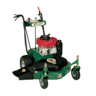
T h a n k Y o u f o r S e l e c t i n g
The Powerful Self-Propelled Billy Goat Mower
Operator Owner's Manual
FM3300 & FM3300E
3
Engine: HP
Engine:Type
Engine: Fuel cap.
Engine: Oil Cap.
Weight: Unit
Weight: Shipping
Specifi cations
FM3300
13.0 HP (9.7 kW)
B&S INTEK OHV
3.0 qt. (2.8 L)
1.5 qt. (1.4 L)
267 # (121 Kg)
410 # (186 Kq)
UNIT SIZE:
OVERALL LENGTH - 57"(1.44 m)
OVERALL WIDTH - 43" (1.09 m)
OVERALL HEIGHT - 47" (1.19 m)
Page 1 of 20
FM3300E
13.0 HP (9.7 kW)
B&S INTEK OHV
ELECTRIC START
3.0 qt. (2.8 L)
1.5 qt. (1.4 L)
277 # (126 Kg)
420 # (191 Kq)
Form No. F061604A
Advertisement
Table of Contents

Related Manuals for Billy Goat FM3300


Summary of Contents for Billy Goat FM3300
- Page 1 Easily convert your mower to bag grass and leaves. Transaxle Guard Kit P/N 520155 To protect the transaxle from accidental contact from concrete curbs or other hazards. Part No. 520141 FM3300 & FM3300E Specifi cations FM3300 Engine: HP 13.0 HP (9.7 kW) Engine:Type B&S INTEK OHV...
-
Page 2: In The Interest Of Safety
IN THE INTEREST OF SAFETY BEFORE STARTING ENGINE, READ AND UNDERSTAND THE “ENTIRE OPERATOR'S MANUAL & ENGINE MANUAL.” THIS SYMBOL MEANS WARNING OR CAUTION. DEATH, PERSONAL INJURY AND/OR PROPERTY DAMAGE MAY OCCUR UNLESS INSTRUCTIONS ARE FOLLOWED CAREFULLY. WARNING: to the State of California to cause cancer, birth defects or other reproductive harm. WARNING: DO NOT 1. -
Page 3: General Safety
GENERAL SAFETY For your safety and the safety of others, these directions should be followed: Do not operate this machine without fi rst reading owner's manual and engine manufacturer's manual. Use of Ear Protection is recommended while operating this machine. Use of Eye and Breathing protection is recom- mended when using this machine. -
Page 4: Put Oil In Engine Before Starting
ASSEMBLY Read all safety and operating instructions before assembling or starting this unit. PUT OIL IN ENGINE BEFORE STARTING. DISCONNECT SPARK PLUG WIRE BEFORE ASSEMBLING UNIT. Your Billy Goat Mower is shipped from the factory in one crate, completely assembled except for the handles and console assembly. -
Page 5: Engine Labels
LITERATURE ASSY Literature Checklist Check Owner's Owner's Manual Manual 520141 900407 Ty Wrap Qty 4 CONTROLS Throttle Control ENGINE LABELS Briggs & Stratton Part No. 520141 P/N 520137 33" TRIPLE BLADE ELECTRIC START MODEL Check Warranty Card 400972 33" TRIPLE BLADE 33"... -
Page 6: Instruction Labels
INSTRUCTION LABELS These labels should be included on your Billy Goat Finish Mower. If any of these labels are damaged, replace them before putting this equipment into operation. Item and part numbers are given to help in ordering replacement labels.. WARNING EXPLOSIVE FUEL STOP ENGINE AND ALLOW T O... -
Page 7: Cutting Operation
OPERATION INTENDED USE: This unit is mainly designed for cutting grass. Some overgrown weeds, and taller grass may also be cut. Be sure to inspect work area and machine before operating. Make sure that all operators of this equipment are trained in general machine use and safety. Like all mechanical tools, reasonable care must be used when operating machine. -
Page 8: Cutting Height Adjustment
OPERATION continued 16.3 CUTTING HEIGHT ADJUSTMENT CAUTION: DO NOT make cutting height adjustment when engine is running. Cutting height can be adjusted from 1.5" to 4" by placing spacers above or below caster spindles. For easiest adjust- ment change the height on one side at a time. To change cutting height, tilt the unit back, remove lynch pin, remove all spacers then set if off to the side, remove caster rig, add or subtract spacers, reinstall caster rig, place remainder... - Page 9 OPERATION continued PROPULSION 16.5 This unit is self-propelled, and is controlled by an operator presence control. To engage the wheel drive, first push down on the BRAKE RELEASE lever on the right side, then lift the operator's DRIVE lever on the right side against operator's handle.
-
Page 10: Maintenance History
MAINTENANCE Use only a qualifi ed mechanic for any adjustments, disassembly or any kind of repair . WARNING: TO AVOID PERSONAL INJURY, ALWAYS TURN MACHINE OFF, MAKE SURE ALL MOVING PARTS COME TO A COM- PLETE STOP. Note: Blade, blade brake puck, transaxle brake, and drive belts are normal wear items. These should be inspected on a regular basis and replaced if worn. -
Page 11: Cable Adjustments
MAINTENANCE continued 17.1 CABLE ADJUSTMENTS CAUTION: DO NOT make cable adjustment when engine is running. Disconnect spark plug wire before making any adjustments. Brake Adjustment The brake control cable is spring loaded and requires no adjustment; however, the transaxle brake is adjustable. When the mower is in neutral and can be pushed by hand without depressing the brake lever, the transaxle brake needs adjustment. -
Page 12: Blade Removal / Sharpening
MAINTENANCE continued BLADE REMOVAL / SHARPENING 17.4 NOTE: When sharpening the blade it is a good idea to check the balance of the blade. A properly balanced blade will increase life of the bearings and other components. Tools required: ratchet, 3/4” inch socket, torque wrench, ade- quate support, block to inhibit blade rotation. -
Page 13: Spindle Drive Belt
MAINTENANCE continued BELT REPLACEMENT continued 17.5 Blade Drive Belt Replacement 13. Reinstall the left and right belt guide fi ngers under the engine base using all fasteners in the exact order they were removed. NOTE: Before installing the fasteners inspect them for wear and replace as necessary. -
Page 14: Brake Puck Replacement
MAINTENANCE BRAKE PUCK REPLACEMENT 17.6 Tools Required: 5/32” Allen wrench; 3/8” wrench. 1. Remove the spark plug wire. 2. Remove the belt deck cover. 3. Remove the brake spring (A) and control cable spring (B) (see fi gure 17-10). 4. Remove the blade drive belt (C) from the drive pulley (D). 5. -
Page 15: Parts Drawing
520081 520088 520100-S 1 520109 610308-P 3 900327 Page 15 of 20 PARTS DRAWING FM3300 & FM3300E DECK ASSEMBLY DESCRIPTION FM3300E QTY PART NO. BOLT CARRIAGE 3/8-16X1” ZP 8024058 5 BOLT CARRIAGE 3/8-X 1 1/4 8024059 SCREW CAP 1/4 - 20 X 7"... - Page 16 WASHER SPLIT LOCK 5/16" 520114 NUT JAM 5/16" POSITIVE CABLE 10" WASHER 3/8" FLATCUT 8041051 4 WASHER #10 FLATCUT Page 16 of 20 PARTS DRAWING FM3300 & FM3300E ENGINE ASSEMBLY FM3300E QTY PART NO. 790133 850132 850443 890359 890408 900327...
- Page 17 NUT JAM 1/4-20 850408 RING SNAP 5/8 T.A. 8024023 1 8024058 2 WASHER 0.906 OD X 0.656 Page 17 of 20 PARTS DRAWING FM3300 & FM3300E DRIVE ASSEMBLY TO CONSOLE 156 158 FM3300E QTY PART NO. 8041053 1 8041013 1...
- Page 18 520084-S 1 520085 520086 520091-S 1 520093-S 1 520094 520095 520096 520097 Page 18 of 20 PARTS DRAWING FM3300 & FM3300E HANDLE ASSEMBLY DESCRIPTION FM3300E QTY PART NO. GRIP LEVER ORANGE 520098 CONSOLE FM W/ LABELS 520146 CUP HOLDER 520102...
-
Page 19: Mulching Kit
ACCESSORIES GRASS CATCHER KIT 520142 19.1 Purpose: Easily convert your mower to bag grass and leaves. Item No. MULCHING KIT 520144 19.2 Purpose: Reduces lawn clippings to fi ne nutrient-rich particles that fi lter down to the soil. Item No. Part No. -
Page 20: Troubleshooting
TROUBLESHOOTING NOTE: For repairs beyond the minor adjustments listed below, contact your nearest authorized service dealer. Problem The engine will not start 1. Engine not properly primed. 2. Out of gasoline or bad or old gasoline. 3. Spark plug wire disconnected. 4.
Need help?
Do you have a question about the FM3300 and is the answer not in the manual?
Questions and answers