Table of Contents
Advertisement
Available languages
Available languages
Quick Links
MCSE Series
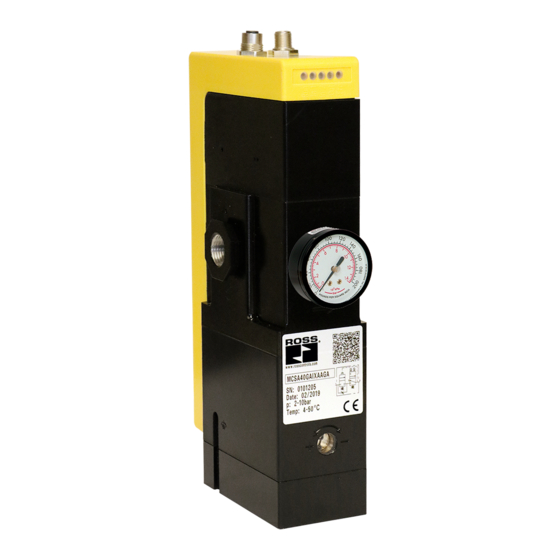
MCSE Series – Safety Exhaust (Dump) Control Reliable Double Valves
Serie MCSE – Redundantes Sicherheitsventil mit internen Überwachung, Doppelventile mit zuverlässiger Steuerung
Serie MCSE – Escape de seguridad (vaciado) Válvulas dobles de control fiables
Série MCSE – Electrovane de Sécurité Modulaire Double Corps
Serie MCSE – Scarico di sicurezza (discarica) controllo affidabile valvole doppie
Серия MCSE – Безопасный выпуск (сброс) Надежные двойные регулирующие клапаны
Operating Instructions l Betriebsanleitung
Instrucciones de servicio I Instructions d'utilisation
Istruzioni operative I Инструкция по эксплуатации
Declaration of CE Conformity and Certifications available for download at www.rosscontrols.com.
Die CE-Konformitätserklärung und CE-Zertifizierungen können unter www.rosscontrols.com heruntergeladen werden.
Declaración de Conformidad CE y Certificaciones disponibles para descargar en www.rosscontrols.com.
Déclaration de conformité CE et certifications disponibles au téléchargement sur le site www.rosscontrols.com.
Dichiarazione di conformità CE e certificazioni disponibili per il download all'indirizzo www.rosscontrols.com
Декларация и сертификаты соответствия нормам ЕС доступны для скачивания на сайте www.rosscontrols.com.
RC-MCSE-OI
EN/DE/ES/FR/IT/RU
www.rosscontrols.com
Advertisement
Table of Contents

Related Manuals for Ross MCSE Series


Summary of Contents for Ross MCSE Series
- Page 1 RC-MCSE-OI EN/DE/ES/FR/IT/RU MCSE Series MCSE Series – Safety Exhaust (Dump) Control Reliable Double Valves Serie MCSE – Redundantes Sicherheitsventil mit internen Überwachung, Doppelventile mit zuverlässiger Steuerung Serie MCSE – Escape de seguridad (vaciado) Válvulas dobles de control fiables Série MCSE – Electrovane de Sécurité Modulaire Double Corps Serie MCSE –...
- Page 2 FOR NPT THREAD: ANSI/ASME B1.20.1 FEMALE PORT FITTING MALE PORT FITTING None (plugged port) Start-Button NCNO FOR G THREAD: ISO 228-1 Combination Solenoid Sensor ROSS FRL’s MD Series Dimension – Inches (mm) IMENSIONAL RAWINGS MCSE 167.8 ± 2.5 (2x) G1 (6.60 ± 0.10) 28.5 Sintered Bronze (2.28)
- Page 3 ENGLISH MCSE Series Operating Instructions 24 V DC 0 V GND 24 V Figure 6. Figure 1. Signal Sequence when 41, 42 Principle Use of the Switching On Signal Output RUN-LED 24 V DC 0V GND 24 V Figure 2.
-
Page 4: About This Documentation
2 “Notes on safety” Soft Start The MCSE Series double valves have a soft start function (soft start). The function of the soft start module is that the output pressure increases slower than normal during pressurization, until it reaches approx. 50% of the inlet pressure. The valve then opens fully at this point and fills the system with the full flow rate. -
Page 5: Product Identification
In case of technical problems or a required service, please contact your local • Do not plug the valve exhaust port. ROSS representative. If used properly, the MCSE Series double valves will not • Use only high-flow, non-clogging silencers, with similar or higher specifications as require maintenance. -
Page 6: Commissioning And Operation
ENGLISH MSCE Series Operating Instructions 7.3.5. Principle Wiring for NCNC or NCNO Control When using the NCNC or NCNO control, the safety switches are supplied by the clock signal (S21, S11). Safety input 1 (S12) is connected with S11 via the switch. Safety input 2 (S22) is connected with S21 via the switch. - Page 7 ENGLISH MCSE Series Operating Instructions The MCSE safety valve is supplied with 24 V DC at time 1. The RUN LED and all other the pressurized state (MCSE=1) at time 4. OUT LED illuminates and indicates the LEDs flash briefly when switched on. The device performs a self-test. This self-test activated state.
-
Page 8: Care And Maintenance
ENGLISH MSCE Series Operating Instructions The following table shows an overview of LED displays with the corresponding function. • Regularly check that the seals are in perfect order. • Immediately exchange the MCSE safety valve if the seals are defective. Display Type Function Color... -
Page 9: Technical Specifications
• Disassemble the MCSE safety valve as described in chapter 10 “Disassembly and systems to reduce noise emissions. Exhausting of the valve may not be restricted. We Exchange” and send it to ROSS CONTROLS. You can find the address on the back of do not recommend using the product without silencers. - Page 10 INNENGEWINDEANSCHLUSS AUSSENGEWINDEANSCHLUSS FÜR NPT GEWINDE: ANSI/ASME B1.20.1 Start-Taste NCNO FÜR G GEWINDE: ISO 228-1 PIN-Konfiguration Keine (verschlossener Magnet Sensor Anschluss) ROSS FRL’s MD Serie Zoll (mm) ASSZEICHNUNGEN BMESSUNGEN MCSE 167,8 ± 2,5 (2x) G1 (6,60 ± 0,10) 28,5 Gesinterte Bronze...
- Page 11 DEUTSCH Betriebsanleitung Serie MCSE 24 V DC 0 V GND 24 V 41, 42 Abbildung 1. Abbildung 6. Prinzip der Verwendung Signalfolge beim des Signalausgangs Einschalten RUN-LED 24 V DC 0V GND 24 V Abbildung 7. Abbildung 2. 41, 42 Signalfolge bei Auftreten Prinzip der Verdrahtung eines Fehlers...
-
Page 12: Über Diese Dokumentation
(Übersetzung des Originals) (Original Version) Zeigt eine mögliche Gefahr an, die bei Nichtvermeidung zu schweren Produkt: ROSS® Doppelventil MCSE Product: ROSS® double valve MCSE WARNUNG oder tödlichen Verletzungen führen kann. Die alleinige Verantwortung für die Ausstellung dieser Konformitätserklärung trägt der Hersteller. - Page 13 Diagnosedeckungsgrad von 99 % erzielen. zustellen oder zu reparieren. Bei technischen Problemen oder einem erforderli- chen Service wenden Sie sich bitte an Ihren lokalen ROSS-Vertreter. Bei korrekter 2.1.4. Unsachgemäße Nutzung Verwendung erfordern die Doppelventile der MCSE-Serie keine Wartung. Sofern nicht anders gefordert, empfiehlt ROSS®...
-
Page 14: Inbetriebnahme Und Betrieb
DEUTSCH Betriebsanleitung Serie MCSE Hinweis: Die fehlerfreie Funktion des MSCE-Sicherheitsventils ist nicht gewährleistet, wenn der Versorgungsdruck nicht zwischen 2 bar (29 psig) und bis zu 10 bar (145 psig) liegt. 1. Schließen Sie die Druckleitung für den Versorgungsdruck an den Anschluss 1 (1, IN) an. - Page 15 DEUTSCH Betriebsanleitung Serie MCSE 8.1.1. Funktion „Druckaufbau“ SE-Sicherheitsventil zur Zeit 4 in den druckbeaufschlagten Zustand (MCSE = 1). Die OUT LED leuchtet auf und zeigt den aktivierten Zustand an. Die Zeit für das Überwa- Wenn das MCSE Sicherheitsventil die Maschinen mit Druck beaufschlagen soll, müs- chungssignal X2 liegt zwischen minimal 0,03 s und maximal 3 s.
-
Page 16: Pflege Und Wartung
DEUTSCH Betriebsanleitung Serie MCSE 9. Pflege und Wartung Das Gerät arbeitet zur Zeit 1 fehlerfrei. Im Falle einer Störung (3) öffnet der Signalaus- gang (41, 42 = 0) zur Zeit 2. Die ERR-LED zeigt durch eine Abfolge von langen und kurzen Blinksignalen einen Fehlercode an. -
Page 17: Fehlerbehebung
• Das Sicherheitsventil MCSE wie in Kapitel 10 „Demontage und Austausch“ be- Stoßfestigkeit (DIN EN 60068-2-27): 30 g mit 18 ms Dauer. schrieben demontieren und an ROSS CONTROLS senden. Die Adresse finden Sie Stoßwellenform: Sinus-Halbwelle. auf der Rückseite der Bedienungsanleitung. - Page 18 PARA EL HILO G: ISO 228-1 de configuración PIN PUERTO HEMBRA PUERTO MACHO Botón de inicio NCNO (puerto enchufado) Solenoide Sensor ROSS serie MD FRL Dimensión – Pulgadas (mm) LANOS DE DIMENSIONES Válvula 167.8 ± 2.5 (2x) G1 (6.60 ± 0.10) 28.5 Bronce sinterizado (2.28)
- Page 19 ESPAÑOL Instrucciones de servicio Serie MCSE 24 V DC 0 V GND 24 V 41, 42 Figura 6. Secuencia de señales Figura 1. durante la conexión Principio de uso de la salida de la señal RUN-LED 24 V DC 0V GND 24 V Figura 2.
-
Page 20: Acerca De Esta Documentación
(Original Version) (Versión original) Indica un posible peligro que podría causar lesiones graves ADVERTENCIA Product: ROSS® double valve MCSE Producto: ROSS® válvula doble MCSE o incluso mortales de no evitarse. Esta declaración de conformidad se expide bajo la exclusiva responsabilidad del fabricante... -
Page 21: Identificación Del Producto
Instale la válvula de forma que quede protegida contra los efectos de los productos químicos. ROSS CONTROLS no se hace responsable de los daños que resulten de un uso ¡Daños en el dispositivo por almacenamiento a temperaturas inadecuadas! inadecuado. El usuario es el único que asume los riesgos de un uso inadecuado del producto. -
Page 22: Puesta En Marcha Y Funcionamiento
ESPAÑOL Instrucciones de servicio Serie MCSE 7.3.4. Principio de cableado para el control PP Los contactos del conector XPS M12 macho tienen la siguiente asignación de pines: Al utilizar el mando PP, las entradas de seguridad 1 y 2 deben conectarse cada una con una señal de salida segura. - Page 23 ESPAÑOL Instrucciones de servicio Serie MCSE 8.1.6. Secuencia de señales para el control NCNO El escape de la línea de operación es el estado seguro. No debe restringirse el escape de la válvula. Durante el control por NCNO de la válvula de seguridad MCSE se produce la siguiente 8.1.3.
-
Page 24: Cuidado Y Mantenimiento
ESPAÑOL Instrucciones de servicio Serie MCSE 9. Cuidado y mantenimiento Parpadea Causa del error Largo Corto ATENCIÓN Tensión de alimentación demasiado baja ¡Daños en el producto debido al uso de disolventes y agentes de limpieza agresivos! Tensión de alimentación demasiado alta El producto puede dañarse si se lava con un disolvente o un agente de limpieza agresivo. -
Page 25: Solución De Problemas
• Desmonte la válvula de seguridad MCSE como se describe en el capítulo 10 Resistencia a la vibración (DIN EN 60068-2-6): 0.35 mm ± 0.05 mm desplazamiento "Desmontaje y cambio" y envíela a ROSS CONTROLS. La dirección se encuentra en el reverso de las instrucciones de funcionamiento. - Page 26 Bouton de Combinaison POUR FILETAGE G ISO 228-1 Néant (port obturé) démarrage NCNC Électrovanne Capteur Bouton de Série MD de ROSS FRL démarrage NCNO Dimension – Pouces (mm) CHÉMAS DIMENSIONNELS MCSE 167,8 ± 2,5 (2x) G1 (6,60 ± 0,10) 28,5 Bronze fritté...
- Page 27 FRANÇAIS Instructions d‘utilisation de la Série MCSE 24 V DC 0 V GND 24 V Figure 6. 41, 42 Séquence de signaux Figure 1. à l’activation Principe d’utilisation de la sortie de signaux RUN-LED 24 V DC 0V GND 24 V Figure 7.
-
Page 28: À Propos De Cette Documentation
(Traduction de la version d'origine) Indique un danger grave et imminent qui résultera en blessures graves Product: ROSS® double valve MCSE Produit : Double vanne ROSS® MCSE DANGER voire mortelles s’il n’est pas évité. Cette déclaration de conformité est publiée sous la seule responsabilité du fabricant This declaration of conformity is issued under the sole responsibility of the manufacturer Indique un danger possible qui peut résulter en blessures graves voire... - Page 29 2.1.3. Couverture du diagnostic la vanne. En cas de problèmes techniques ou si une intervention d’entretien est requise, veuillez contacter votre représentant local ROSS. Si elles sont utilisées Il est possible d'atteindre une couverture de diagnostic de 99 % en intégrant comme il correctement, les vannes MCSE ne réclament aucune maintenance.
-
Page 30: Mise En Service Et Utilisation
FRANÇAIS Instructions d‘utilisation de la Série MCSE 7.2. Installation pneumatique L’entrée de démarrage X2 n’est pas active pendant une commande effectuée avec PP ou PM. La vanne de sécurité MCSE procède à un démarrage automatique. L’entrée de Montage du capteur ou de la jauge de pression (en option) démarrage X2 doit être raccordée à... - Page 31 FRANÇAIS Instructions d‘utilisation de la Série MCSE Vérifiez que toutes les prises sont connectées correctement. Définissez toujours Si le signal de démarrage X2 passe de 0 V à 24 V (côté positif) à l’heure 3, puis l'alimentation en air comprimé sur un niveau permettant de respecter la pression de repasse de 24 V à...
-
Page 32: Entretien Et Maintenance
ITALIANO Serie MCSE Istruzioni operative 9. Entretien et maintenance Le dispositif fonctionne sans défaillance à l’heure 1. La sortie de signaux (41, 42=0) s’ouvre à l’heure 2 si une défaillance (3) survient. La DEL ERR indique un numéro de ATTENTION défaillance par le biais d'un clignotement qui consiste en séquences de clignotements longs et courts. -
Page 33: Dépannage
• Désassemblez la vanne de sécurité MCSE en suivant la description fournie au Principe de test : GS-IFA-M07, avril 2017. chapitre 10 « Désassemblage et remplacement » et envoyez-la à ROSS CONTROLS. Fonctions de sécurité : « Évacuation sûre » et « Protection contre tout démarrage L'adresse se trouve au dos des instructions d’utilisation. - Page 34 PER FILETTATURA NPT: ANSI/ASME B1.20.1 Nessuno (porta Pulsante di avvio NCNO Combinazione PER FILETTATURA G: ISO 228-1 collegata) Solenoide Sensore Serie MD della ROSS FRL Dimensione – Pollici (mm) ISEGNI DIMENSIONALI MCSE 167,8 ± 2.5 (2x) G1 (6.60 ± 0.10)
- Page 35 ITALIANO Serie MCSE Istruzioni operative 24 V DC 0 V GND 24 V Figura 1. 41, 42 Figura 6. Principio di utilizzo dell'uscita del segnale Sequenza di segnali durante l'accensione RUN-LED 24 V DC 0V GND 24 V Figura 7. Figura 2.
- Page 36 (Versione originale) Indica un pericolo imminente e grave che può comportare gravi PERICOLO Product: ROSS® double valve MCSE Prodotto: Valvola doppia ROSS® MCSE lesioni, persino mortali, nel caso in cui non venga evitato. La presente dichiarazione di conformità è stata emessa sotto l'esclusiva responsabilità del produttore This declaration of conformity is issued under the sole responsibility of the manufacturer Indica un possibile pericolo che può...
-
Page 37: Contenuto Dell'imballo
Distruzione di componenti! ROSS CONTROL non si assume alcuna responsabilità per danni derivanti da un Le sostanze chimiche possono danneggiare la superficie, i contrassegni e le guarnizioni del uso improprio. Il solo utente si assume i rischi di un uso improprio del prodotto. - Page 38 ITALIANO Serie MCSE Istruzioni operative 7.3. Collegamenti pneumatici e elettrici L’attuazione del pulsante è monitorata. Il pulsante può avere un tempo di attuazione massimo tra 0.03 s e 3 s. Il controllo non viene eseguito se viene superato il tempo. Collegamenti pneumatici Requisito: La pressione di mandata deve sempre essere tra 29 psig (2 bar) e 145 psig I contatti sulla spina X2D, ingressi di sicurezza M12 femmina presentano la seguente...
- Page 39 ITALIANO Serie MCSE Istruzioni operative è acceso. Il LED IN 1 e il LED IN 2 lampeggiano velocemente e indicano che gli ingressi 8.1. Mettere in funzione la valvola di sicurezza MCSE dei segnali 1 e 2 non sono stati azionati contemporaneamente. Procedere come di seguito descritto per mettere in funzione la valvola di sicurezza MCSE: Se il segnale iniziale X2 cambia da 0 V a 24 V (fianco positivo) al tempo 3 e ricambia da 1.
-
Page 40: Cura E Manutenzione
ITALIANO Serie MCSE Istruzioni operative 9. Cura e manutenzione Il dispositivo funziona senza guasti al tempo 1. L’uscita del segnale (41, 42=0) apre al tempo 2 se si verifica un errore (3). Il LED ERR indica un numero di guasto lampeggiando ATTENZIONE con sequenze lunghe e corte. -
Page 41: Risoluzione Dei Problemi
• Smontare la valvola di sicurezza MCSE come descritto nel capitolo 10 “Smontaggio Tempo medio tra i guasti pericolosi: Vedere B della libreria ROSS SISTEMA. e sostituzione” e spedirla a ROSS CONTROLS. L’indirizzo è riportato sul retro delle Guasti di cause comuni - CCF: > 65. istruzioni operative. - Page 42 РУССА M SE КОДОВОЕ ОБОЗНАЧЕНИЕ ИЗДЕЛИЯ — КЛАПАН МОНТАЖ MCSE Версия Серия Напряжение Размер портов СС КА модификации 24 В пост. тока MCSE ПРИМЕ АНИ Клапан Устройство Версия Резьба Мониторинг Момент измерения затяжки (τ) Коммуникация BSPP Внутренний (Макс.) давления Нет Манометр...
- Page 43 РУССА M SE 24 V DC 0 V GND 24 V Рисунок 6. Рисунок 1. 41, 42 Последовательность Принцип сигналов при включении использования выходного сигнала RUN-LED 24 V DC 0V GND 24 V Рисунок 7. 41, 42 Последовательность Рисунок 2. сигналов...
-
Page 44: Правила Техники Безопасности
• Тип или источник опасности: (Original Version) (Оригинальная версия) • Последствия: Product: ROSS® double valve MCSE SS MCSE • Меры по предотвращению опасности: Эта декларация соответствия выдается под исключительную ответственность производителя This declaration of conformity is issued under the sole responsibility of the manufacturer... -
Page 45: Содержимое Упаковки
РУССА M SE 3. Обозначение изделия ( ommon ause Failures, . 42. R SS 4. Необходимые условия при эксплуатации изделия , . . 4.1. Квалификация персонала 5. Содержимое упаковки R SS ® • Д M SE войной клапан серии 2.1.3. Диагностическое покрытие 6. - Page 46 РУССА M SE 7.3. Пневматические и электрические соединения Пневматические соединения MS E (1, I ). 2 (2, 7.3.4. Принципиальная схема для управления PP Электрические соединения . 2, . 43. 7.3.5. Принципиальная схема для управления NCNC или NCNO (S21, S11). 1 (S12) 2 (S22) M SE.
- Page 47 РУССА M SE 8.1.1. Функция «Нагнетание давления» M SE (M SE 1) M SE . 0,03 . 3 . (1 2) M SE M SE (M SE 0). M SE (M SE 0) 8.1.2. Функция «Сброс давления» M SE (1 2) M SE 8.1.6.
- Page 48 РУССА M SE . 43). (41, 42 0) (3). Примечание. 9. Уход и техническое обслуживание 6 (7, . 1,0 ). ВНИМАНИЕ! Возможность повреждения изделия при использовании растворителей и агрессивных Мигающие сигналы Светодиод Причина ошибки чистящих средств! Длинный Короткий S12 S22 Возможность...
-
Page 49: Поиск И Устранение Неисправностей
РУССА M SE 12. Технические требования Конструкция: Управление: Замена MCSE Рабочая среда: 573-1 0...1 M SE M SE, 11. Поиск и устранение неисправностей Рабочий диапазон давлений: 120 F ( Температура окружающей/технологической среды: ПРЕДУПРЕЖДЕНИЕ! 573-3, Опасность травмирования при разборке клапана! Эталонное напряжение: 24 Электрические... - Page 50 www.rosscontrols.com...
- Page 51 www.rosscontrols.com...
- Page 52 Printed in the U.S.A. – Rev. 04/27/20, © 2020 ROSS CONTROLS . All Rights Reserved. Content subject to change. Form RC-MCSE-OI ® Gedruckt in den U.S.A. – Rev. 27.04.2020, © 2020 ROSS CONTROLS . Alle Rechte vorbehalten. Änderungen vorbehalten.Form RC-MCSE-OI ®...
Need help?
Do you have a question about the MCSE Series and is the answer not in the manual?
Questions and answers