Table of Contents
Advertisement
Quick Links
Advertisement
Table of Contents

Related Manuals for Ross GearLite MUX-9258-A


Summary of Contents for Ross GearLite MUX-9258-A
- Page 1 MUX-9258-A User Guide...
- Page 2 Ross has become well known for the Ross Video Code of Ethics. It guides our interactions and empowers our employees. I hope you enjoy reading it below. If anything at all with your Ross experience does not live up to your expectations be sure to reach out to us at solutions@rossvideo.com.
- Page 3 Copyright ©2018 Ross Video Limited, Ross®, and any related marks are trademarks or registered trademarks of Ross Video Limited. All other trademarks are the property of their respective companies. PATENTS ISSUED and PENDING. All rights reserved. No part of this publication may be reproduced, stored in a retrieval system, or transmitted in any form or by any means, mechanical, photocopying, recording or otherwise, without the prior written permission of Ross Video.
-
Page 4: Environmental Information
To avoid the potential release of those substances into the environment and to diminish the need for the extraction of natural resources, Ross Video encourages you to use the appropriate take-back systems. These systems will reuse or recycle most of the materials from your end-of-life equipment in an environmentally friendly and health conscious manner. - Page 5 Company Address Ross Video Limited Ross Video Incorporated 8 John Street P.O. Box 880 Iroquois, Ontario Ogdensburg, New York Canada, K0E 1K0 USA 13669-0880 General Business Office: (+1) 613 4886 Fax: (+1) 613 4425 ...
-
Page 7: Documentation Conventions
IP Address, Subnet Mask, and Gateway for your MUX-9258-A. Contacting Technical Support At Ross Video, we take pride in the quality of our products, but if problems occur, help is as close as the nearest telephone. MUX-9258-A User Guide (v2.0) - Page 8 Our 24-hour Hot Line service ensures you have access to technical expertise around the clock. After-sales service and technical support is provided directly by Ross Video personnel. During business hours (Eastern Time), technical support personnel are available by telephone. After hours and on weekends, a direct emergency technical support phone line is available.
-
Page 9: Before You Begin
Before You Begin If you have questions pertaining to the operation of MUX-9258-A, contact us at the numbers listed in the section “Contacting Technical Support” on page 7. Our technical staff is always available for consultation, training, or service. Overview The MUX-9258-A provides a cost effective miniature solution to multiplex four AES/EBU digital audio signals into a 3G/HD/SD-SDI signal. - Page 10 10 • Before You Begin MUX-9258-A User Guide (v2.0)
-
Page 11: Hardware Overview
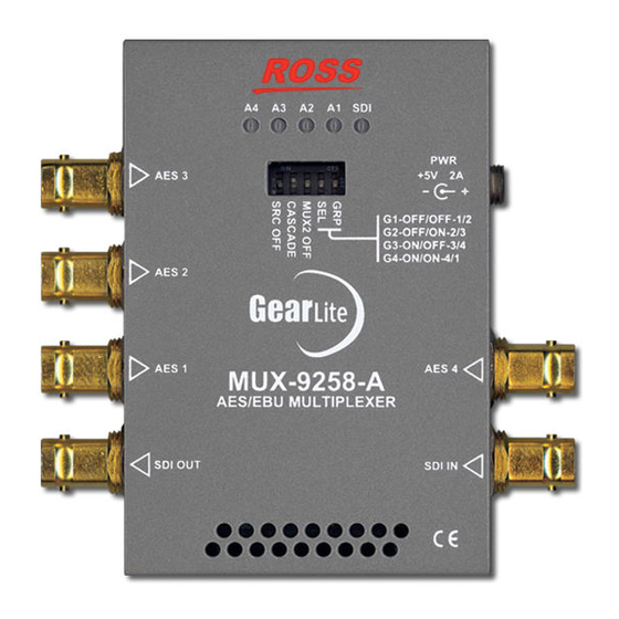
Hardware Overview This chapter presents information on the MUX-9258-A hardware components and features. Chassis Faceplate Overview The chassis faceplate of the MUX-9258-A provides a silk-screen map of the connections available. Figure 3.1 illustrates the MUX-9258-A faceplate label. The chassis of the MUX-9258-A also includes status LEDs that display the status of SDI signal status, and audio status. -
Page 12: Sdi Connections
AES IN 3 AES IN 2 AES IN 1 AES IN 4 Bottom Bottom Figure 3.3 Left Side of Module — AES Inputs Figure 3.4 Right Side of Module — AES Inputs SDI Connections The MUX-9258-A provides a BNC for one SDI output and one SDI input. (Figure 3.5 and Figure 3.6) SDI OUT SDI IN Bottom... - Page 13 Signal Status LEDs The chassis faceplate of the MUX-9258-A includes five LEDs that report the SDI and signal status information and the presence of audio. Refer to Figure 3.7 for the LED locations. Signal Status LEDs A GAIN B GAIN AES 3 Figure 3.7 MUX-9258-A —...
-
Page 14: Dip Switches
DIP Switches The MUX-9258-A provides a block of five DIP switches located on the front panel, near the top. These switches are used to configure the unit for various modes of operation (Figure 3.8) A GAIN B GAIN AES 3 DIP SW 1-5 Figure 3.8 MUX-9258-A —... -
Page 15: Physical Installation
Physical Installation If you have questions pertaining to the installation of MUX-9258-A, please contact us at the numbers listed in the section “Contacting Technical Support” on page 7. Our technical staff is always available for consultation, training, or service. For More Information on... •... - Page 16 SURFACE MOUNT STRIPS SERIAL NUMBER LABEL PROTECTIVE BACKING FILM Figure 4.1 Surface Mount Installation Option Remove the Protective Backing Film from the other side of the VELCRO® brand Surface Mount Strips. Press the chassis into position on the surface you want to mount it to. Non-Slip Pads Four non-slip adhesive pads have been supplied for desktop placements.
- Page 17 Cabling This chapter provides an overview of connecting external devices to the MUX-9258-A. AES Input Cabling Refer to Figure 5.1 for AES input cabling designations. A GAIN B GAIN AES IN 3 AES 3 AES IN 2 AES 2 AES IN 1 AES IN 4 AES 1 AES 4...
- Page 18 Power Adapter and Supply Connect the PS-9000 power adapter to the power supply connector. The PS-9000 provides regulated +5V DC (5%) @ up to 2A. The DC power cord has a locking connector that securely fastens into the power supply DC jack on the MUX-9258-A.
-
Page 19: Using The Dip Switches
Setup The DIP Switches on the bottom of the MUX-9258-A enable you to configure the audio groups, enable Sample rate Conversion, how to embed the audio, and configure the audio multiplexer. For More Information on... • the location of the DIP Switches, refer to the section “DIP Switches” on page 14. Using the DIP Switches Figure 6.1 shows the DIP Switches set in the ON () position. -
Page 20: Audio Mode
Audio Mode Table 6.3 outlines how to configure SW2 to specify the audio mode. Table 6.3 Audio Mode Configuration Description The MUX-9258-A strips all incoming audio from the signal before embedding the AES inputs. This is the default. The MUX-9258-A embeds the AES inputs as well as passing ... -
Page 21: Warranty And Repair
This MUX-9258-A User Manual provides all pertinent information for the safe installation and operation of your RossGear Product. Ross Video policy dictates that all repairs to the MUX-9258-A are to be conducted only by an authorized Ross Video Limited factory representative. Therefore, any unauthorized attempt to repair this product, by anyone other than an authorized Ross Video Limited factory representative, will automatically void the warranty. - Page 22 22 • Warranty and Repair MUX-9258-A User Guide (v2.0)
-
Page 23: Technical Specifications
Technical Specifications This chapter provides technical information for MUX-9258-A. Specifications are subject to change without notice. SDI Input and Output Table 8.1 Technical Specifications — SDI Input and Output Item Specifications Standards Accommodated SMPTE 259M SMPTE 292M SMPTE 424M Level 800mV p-p +/- 10% SDI Data Rates... -
Page 24: Specifications
Dimensions Table 8.4 Technical Specifications — Dimensions Item Specifications Physical Dimensions 3.938” x 2.625” x 0.813” (10cm x 6.70cm x 2.10cm) Weight 7.8oz (221g) 24 • Technical Specifications MUX-9258-A User Guide (v2.0)
Need help?
Do you have a question about the GearLite MUX-9258-A and is the answer not in the manual?
Questions and answers