Table of Contents
Advertisement
Quick Links
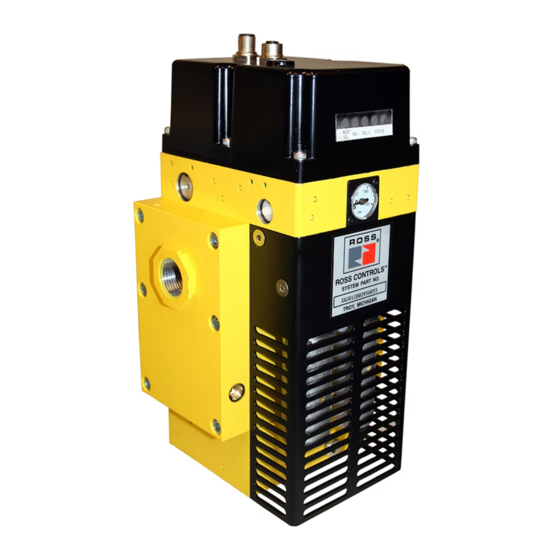
Control Reliable Modular Double Valves
with Integrated Soft Start
Double Valves with Dynamic Monitoring & Memory
Dynamic Monitoring With Memory:
two identical valve elements. Valves lock-out if asynchronous movement of valve elements occurs during
actuation or de-actuation, resulting in a residual outlet pressure of less than 1% of supply.
An Action is Required for Reset:
can be accomplished by the integrated electrical (solenoid) reset or by the manual reset button.
Basic 3/2 Normally Closed Valve Function:
response and high flow capacity. PTFE back-up rings on pistons to enhance valve endurance – operates
with or without inline lubrication.
LED Indication:
Light-emitting diode (LED) indicators of main solenoid operation, reset solenoid operation,
and status indicator condition.
Status Indicator:
Includes a pressure switch with both normally open (NO) and normally closed (NC)
contacts to provide status feedback to the control system indicating whether the valve is in the lockout or
ready-to-run condition.
Transducer (optional):
Silencers:
All models include high flow, clog resistant silencers.
Port Size
Basic Size
Inlet
Outlet
3/4
3/4
8
F3
3/4
3/4
8
*
NPT port threads. For BSPP threads , replace "N" in the model number with a "D", e.g., MDM2CDA55A23.
Valve Dimensions – inches (mm)
F
Valve Wiring
Mounting brackets are required to install valve in the system, see M DM
Construction: Dual Poppet.
Mounting Type: Base mounted.
Pilot Solenoids: According to VDE 0580. Enclosure rating according to
DIN 400 50 IP 65. Three solenoids, rated for continuous duty.
Standard Voltages: 24 volts DC.
Pilot Solenoids Power Consumption (each solenoid):
Primary and reset solenoids: 1.2 watts on DC.
Enclosure Rating: IP65, IEC 60529.
Solenoid & Status Indicator Connection:
M12, 5-pin Male Receptacle, A-Coded.
Ambient Temperature: 15° to 122°F (-10° to 50°C).
Media Temperature: 40° to 175°F (4° to 80°C).
Flow Media: Filtered, lubricated or unlubricated (mineral oils according to
DIN 51519, viscosity classes 32-46); 5-micron recommended.
This valve is not designed for controlling clutch/brake mechanisms on mechanical power presses,
IMPORTANT NOTE:
F3.16
Memory, monitoring, and air flow control functions are integrated into
Cannot be reset by removing and re-applying supply pressure. Reset
Dirt tolerant, wear compensating poppet design for quick
For monitoring of downstream pressure in the system.
Transducer
Valve Model
With
MDM2CNA55A23
Without
MDM2CNA55A21
10.78
(273.8)
5.73
(145.5)
1.63 (41.3)
5.35 (136.0)
5 Pin "A" Code
Female Connector
(N.C. Status Contact)
STANDARD SPECIFICATIONS (for valves on this page):
see DM2
series D for mechanical power press applications.
®
Please read carefully and thoroughly all of the
© 2016, ROSS CONTROLS
C
V
Number*
1 to 2
2 to 3
3.7
8.5
16.3 (7.4)
3.7
8.5
16.1 (7.3)
Outlet
Inlet
5.81 (147.6)
Adjustable Flow Control
BROWN
WHITE
(+24 Volts DC)
(N.O. Status Contact)
1
2
GRAY
5
(Equip. Ground)
4
3
BLACK
BLUE
(Common)
Series C accessories for ordering information page F3.18.
2®
Inlet Pressure: 30 to 150 psig (2 to 10 bar). Under certain circumstances,
such as maximum restriction of the adjustable flow control or a very large
downstream system volume, the minimum inlet pressure may need to be
set up to 60 psig (4 bar) to prevent nuisance valve faults.
Pressure Switch (Status Indicator) Rating: 5 amps at 30 volts DC.
Monitoring: Dynamically, cyclically, internally during each actuating and
de-actuating movement. Monitoring function has memory and requires
an overt act to reset unit after lockout.
Mounting Orientation: Vertically with pilot solenoids on top.
Functional Safety Data: Category 4 PL e; B10d: 20,000,000; PFHd:
7.71x10
-9
; MTTFd: 301.9 (n
Certifications: CE Marked for applicable directives, CSA/UL.
Vibration/Impact Resistance: Tested to BS EN 60068-2-27.
CAUTIONS, WARNINGS
. All Rights Reserved.
®
M DM
2®
Air Dump / Release
4
HSM 15022
Sicherheit seprüft
tested safety
ISO 13849-1:2006
Category 4 PL e
applications
Weight
lb (Kg)
U.S. Patent
No. 6840258, 6840259
(Worldwide Patents
Pending)
Simplified Schematic
WHITE
(Sol 2)
2
1
5 Pin "A" Code
5
Male Connector
3
4
BLUE
(Common)
: 662400).
op
on the inside back cover.
Online Version
Rev. 11/14/16
Series C
3
2
BROWN
(+24 Volts DC)
GRAY
(Reset)
BLACK
(Sol 1)
Advertisement
Table of Contents

Related Manuals for Ross M DM2 C Series


Summary of Contents for Ross M DM2 C Series
- Page 1 DM2 series D for mechanical power press applications. ® IMPORTANT NOTE: CAUTIONS, WARNINGS Please read carefully and thoroughly all of the on the inside back cover. Online Version F3.16 © 2016, ROSS CONTROLS . All Rights Reserved. ® Rev. 11/14/16...
- Page 2 Control Reliable Modular Double Valves M DM Series C 2® with Integrated Soft Start Valve Operation Valve de-actuated (ready-to-run): The flow of inlet air pressure to the inlet chamber of the main valve internals is restricted by a fixed orifice and an adjustable flow control as well as an air piloted 2-way normally closed poppet valve.
- Page 3 Kit Number 2433H77 0.44 3.0 (76.2) (11.1) 3.875 (98.4) IMPORTANT NOTE: CAUTIONS, WARNINGS Please read carefully and thoroughly all of the on the inside back cover. Online Version F3.18 © 2016, ROSS CONTROLS . All Rights Reserved. ® Rev. 11/14/16...
- Page 4 Specify voltage when ordering. Insert voltage code: “W” = 24 volts DC; “Z” = 110-120 volts AC, 50/60 Hz; e.g., RC304-09W. M12 connectors available, consult ROSS. Standard Air Entry Packages supplied with metal bowl and manual drain. For automatic drain insert an “A” before the dash (-) in the model number, e.g., RC304A-09.
- Page 5 Standard Air Entry Packages supplied with metal bowl and manual drain. For automatic drain insert an “A” before the dash (-) in the model number, e.g., RC408A-06. Custom designs available, consult ROSS. Explosion proof solenoid pilot available, for more information consult ROSS. M DM Series C Double Valves with Integrated Soft Start, Manual Lockout L-O-X Valves 2®...
- Page 6 ROSS. information on the back cover). Order Placement For order placement, consult ROSS or your local ROSS distributor. For a current list of countries and local distributors, visit ROSS’ website at www.rosscontrols.com. Online Version © 2016, ROSS CONTROLS ®...
- Page 7 ROSS’ obligation under this warranty is limited to repair or replacement of the product or refund of the purchase price paid solely at the discretion of ROSS and provided such product is returned to ROSS freight prepaid and upon examination by ROSS is found to be defective. This warranty becomes void in the event that product has been subject to misuse, misapplication, improper maintenance, modification or tampering.
Need help?
Do you have a question about the M DM2 C Series and is the answer not in the manual?
Questions and answers