Advertisement
W64
Thank You!
You have purchased a premium-quality ROSS
It is a single-spindle poppet valve built to the highest standards.
With care in its installation and maintenance you can expect it to
have a long and economical service life. So before you go any
further, please take a few minutes to look over the information in
this document. Then, save it for future reference and for the useful
service information it contains.
Please read and make sure you understand all installation instructions before proceeding with the installation.
Additional technical documentation is available for download at rosscontrols.com.
If you have any questions about installation or servicing your valve, please contact ROSS or
your authorized ROSS distributor, see contact information listed at the back of this document,
Pneumatic equipment should be installed only by persons
trained and experienced in such installation.
Air Lines: Before installing a valve in a new or an existing
system, the air lines must be blown clean of all contaminants.
It is recommended that an air filter be installed in the inlet line
close to the valve.
Valve Inlet (Port 1): Be sure that the supply line is of adequate
size and does not restrict the air supply because of a crimp in
the line, sharp bends, or a clogged filter element.
Valve Outlets (Ports 2 & 4): For faster pressurizing and
exhausting of the mechanism being operated by the valve,
locate the valve as close as possible to the mechanism. The
lines must be of adequate size and be free of crimps and
sharp bends.
Valve Exhausts (Ports 3 & 5): Do not restrict exhaust air flow
as this can adversely affect valve performance. However, to
reduce noise you may use an efficient silencer. ROSS silencers
reduce impact noise by as much as 25 dB, and produce little
back pressure.
Electrical Supply: The voltage and hertz ratings of the
valve solenoids (if any) are printed on the solenoids.The
electrical supply must correspond
to these ratings, or the life of
the solenoids will be shortened.
Connections are made with a plug-in
connector to the prongs as shown
the sketch of the pilot below. If
power is supplied by a transformer
it must be capable of handling the
inrush current without significant
voltage drop.
ROSS CONTROLS
®
ISO 5599-1 Valves
Series
pneumatic valve.
®
VALVE INSTALLATION
or visit rosscontrols.com to find your distributor.
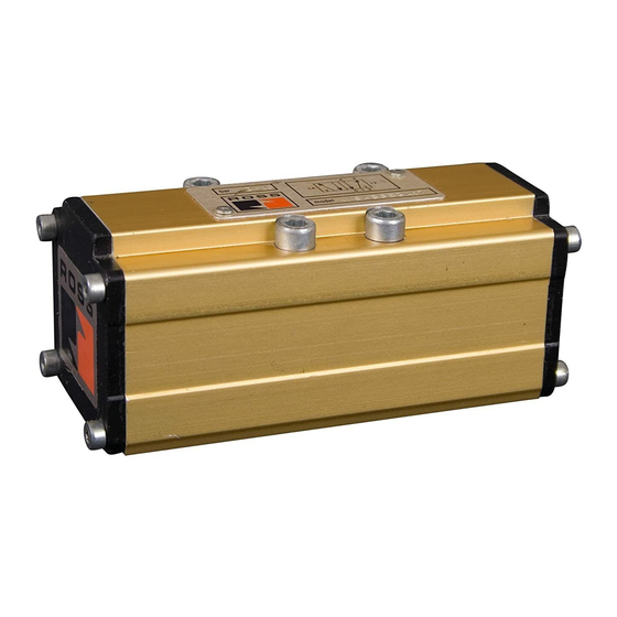
W64 Series valves
are shown on bases,
and with electrical connectors
(purchased separately).
See Valve Specifications on page 2 for information on inrush
current.
Operating Pressures and Temperatures:
ranges for pressure and temperatures are given in the Valve
Specifications on page 2. Exceeding the values shown can
shorten valve life.
Pilot Supply:
Pressure Control: For valves with single remote pressure
control, connect the control line to port 14 in the sub-base
or manifold. For valves with double remote pressure control,
connect the control lines to ports 12 and 14 in the base. See
Valve Specifications on page 2 for required pressures.
Solenoid Control: Pressure for the pilot valves is supplied
from the inlet port. Be sure that port 14 in the base is plugged
or pilot air will escape. If the valve must operate with an inlet
pressure less than the required pilot pressure (see Valve
Specifications on page 2), an external pilot supply of sufficient
pressure must be provided. Connect the external pilot supply
to port 14 in the base.
Non-Air Service: Such applications require an external pilot
supply for solenoid valves. Connect to port 14 in the base.
Consult ROSS Technical Services for fluid media other than air.
Pipe Installation: To install pipe in valve or base ports,
engage pipe one turn, apply pipe thread sealant (tape not
recommended), and tighten pipe. This procedure will prevent
in
sealant from entering and contaminating the valve.
Typical Poppet
Valve Cross Section
Allowable
rosscontrols.com
Advertisement
Table of Contents

Related Manuals for Ross W64 Series


Summary of Contents for Ross W64 Series
- Page 1 Please read and make sure you understand all installation instructions before proceeding with the installation. Additional technical documentation is available for download at rosscontrols.com. If you have any questions about installation or servicing your valve, please contact ROSS or your authorized ROSS distributor, see contact information listed at the back of this document, or visit rosscontrols.com to find your distributor.
- Page 2 The valve can be reconditioned with Cleaning the Valve. If the air supplied to the valve has not been the use of ROSS service kits. well filtered, the interior of the valve may accumulate dirt and See page 3 for information about such kits.
- Page 3 Gasket Service Kit W6456B2411 1017K77 617B11 ROSS would be happy to service this valve for you at its factory repair center. W6456B2412 1014K77 617B11 If you purchased your valve from ROSS please contact ROSS customer service, if you purchased your valve thru an authorized ROSS distributor...
- Page 4 ROSS’ obligation under this warranty is limited to repair or replacement of the product or refund of the purchase price paid solely at the discretion of ROSS and provided such product is returned to ROSS freight prepaid and upon examination by ROSS is found to be defective.
Need help?
Do you have a question about the W64 Series and is the answer not in the manual?
Questions and answers