Ross DM2 C Series Manual
Explosion proof control reliable double valves
Hide thumbs
Also See for DM2 C Series:
- Operating instructions manual (17 pages) ,
- Operating instructions manual (25 pages)
Advertisement
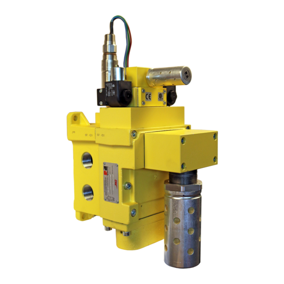
DM
2 ®
Series
Control Reliable Double Valves Basic Size 4, 12 & 30
Thank You!
quality DM
Series C explosion proof double valve with dynamic monitoring and inherent lockout capability for
2®
Category 3 and 4 applications (except press clutch/brake applications). The valve is designed for base mounting
for ease of installation and maintenance. With care in its installation and maintenance you can expect it to have a
long and economical service life. Before you install this valve, read the information in this folder completely, and
save it for future reference.
NOTE: This valve is expressly not intended for use in press clutch/brake applications.
ROSS produces the DM
Series D and a number of other double valve configurations specifically for use with
2®
press clutch/brake applications.
Please read and make sure you understand all installation instructions before proceeding with the installation.
Additional technical documentation is available for download at www.rosscontrols.com.
If you have any questions about installation or servicing your valve, please contact ROSS or your authorized ROSS distributor, see contact
information listed at the back of this document, or visit www.rosscontrols.com to find your distributor.
Pneumatic equipment should be installed only by persons trained and experienced
in such installation.
Application: DM
2®
Series C double valves are intended for use in Category 3
& 4 applications except press clutch/brake applications.
Air Lines: Before installing this valve in a new or existing system, the air lines
must be blown clean of all contaminants. It is recommended that a 5-micron
rated air filter be installed in the inlet line close to the valve.
Valve Inlet (Port 1): Be sure that the supply line is of adequate size and does
not restrict the air supply because of a crimp in the line, a sharp bend, or a
clogged filter element. The air supply must not only provide sufficient pressure
(see Standard Specifications, page 3), but must also provide an adequate flow
of air on demand. Otherwise, the valve elements will be momentarily starved
for air and the valve may fail to operate.
Valve Outlet (Port 2): For faster pressurizing and exhausting of the mechanism
being operated by the valve, locate the valve as close as possible to the
mechanism. The lines must be of adequate size and be free of crimps and
sharp bends.
Valve Exhaust (Port 3):
the exhaust port as this can adversely affect the operation of the valve. The
valves are factory equipped with a properly sized silencer. ROSS silencers
reduce impact noise by as much as 25 dB, and produce little back pressure.
Reset Solenoid: DM
Series C double valves are supplied with a 3/2 normally
2®
closed solenoid valve for reset purposes. Electrical reset signal must be
momentary and of correct voltage.
Electrical Supply: DM
2®
Series C double valves get electrical power through
plug-in connectors. The electrical supply must correspond to the voltage
and hertz ratings of the solenoids. Otherwise, the solenoids are subject to
early failure. If power is supplied by a transformer, the power supply must
be capable of handling the maximum power. See Valve Specifications on
page 3 for information on maximum power.
Operating Pressures and Temperatures: Allowable ranges for pressure and
temperatures are given in the Standard Specifications on page 3. Exceeding
these values can adversely affect performance and shorten valve life.
On first operation, or after repair, the pilot valve supply circuit and inherent
monitoring elements may need to be reset. This reset is accomplished by
applying a momentary air signal to the RESET port or by energizing the
optional reset solenoid momentarily on the valve. After reset, the valve will
then be ready for operation.
The air supply to each pilot valve is controlled by the position of the inlet
poppets. In the ready-for-operation position these poppets are held on their
seats and maintain pilot air flow. During shifting of the valve elements the
poppets move off seat and momentarily allow pilot air to escape to exhaust.
If either valve element fails to operate correctly, the pilot supply to the other
valve element will remain connected to exhaust causing the valve to lockout.
ROSS CONTROLS
®
C
Explosion Proof
You have purchased a premium-quality ROSS
VALVE INSTALLATION
Do not restrict the air flow from
VALVE OPERATION
pneumatic valve. It is a high
®
Pipe Installation: To install pipe in base ports, engage pipe one turn, apply
pipe thread sealant (tape not recommended), and tighten pipe. This procedure
will prevent sealant from entering and contaminating the valve. To install pipe
with parallel threads (e.g., SAE, ISO 228-G, etc.) do not use sealant. After
installing pipe into the base ports, use compressed air to blow any debris out
of the piping, then install the valve onto the base.
Test: After installation or repair and prior to normal use, the internal lockout
feature of the DM
Series C double valve must be tested for proper functioning.
2®
Observe normal equipment operation safety precautions during these tests to
avoid personal injury or damage to equipment.
NOTE: Reset may need to be performed prior to beginning the test procedure.
Also, the valve is designed such that both pilot solenoids must be de-energized
prior to reset, and must remain de-energized until after the reset signal is
removed. Otherwise, the valve will not reset.
A) Electrically energize both pilot solenoids simultaneously, then de-energize
one pilot solenoid. This should result in a valve lockout and prevent the valve
from operating.
B) Energize both solenoids and the valve should remain in the lockout condition.
C) De-energize both pilot solenoids and reset the valve.
D) Electrically energize both pilot solenoids simultaneously again. De-energize
the other pilot solenoid this time. Again, this should result in a lockout.
E) Energize both pilot solenoids. The valve should remain in a lockout condition.
F) De-energize both pilot solenoids and then reset the valve.
After satisfying these tests, energizing both pilot solenoids simultaneously
should result in normal operation.
Fault Indication: The built-in status indicator can be used to signal the machine
controls that a fault has occurred. The status indicator utilizes a pressure switch.
The pressure switch has 4 electrical contacts. During normal operation the
pressure switch is pressurized. A lockout condition depressurizes the switch until
the valve is reset. Contacts 1 and 2 are closed when the switch is depressurized
(normally closed) and contacts 1 and 3 are closed when an adequate pressure
signal is applied to the switch (normally open).
The internal monitoring system will lock out the valve if the time difference
between both elements shifting fully is longer than approximately 125
milliseconds. This timing is preset by restricting-orifices and chambers in
the pilot air circuit.
The main airflow from port 1 to port 2 is via crossflow passages between
both main valves, so that both valve elements must be fully shifted in order
for port 2 to be pressurized.
If the valve locks out, further operation is prevented until the valve has been
reset. Electrical signals to the solenoids must be "off" to allow the valve to
be reset.
The DM2
Series C valve is completely self-contained and does not need
®
an external monitoring system.
Size 12
illustrated
www.rosscontrols.com
Advertisement
Table of Contents

Related Manuals for Ross DM2 C Series


Summary of Contents for Ross DM2 C Series
- Page 1 Additional technical documentation is available for download at www.rosscontrols.com. If you have any questions about installation or servicing your valve, please contact ROSS or your authorized ROSS distributor, see contact information listed at the back of this document, or visit www.rosscontrols.com to find your distributor.
- Page 2 Class I, Zone 1, AEx m II T4, Ta = 60 °C; dust-ignition-proof for Class II/III, Division 1, Groups E, F and G, T4, Ta = 60 °C); Nonincendive Class I, Division 2, Groups A, B, C, D, T4, Ta = 60 °C; Suitable for Class II, III, Division 2, Groups E, F, G, T4, Ta = 60 °C ROSS CONTROLS ®...
- Page 3 VALVE SERVICE ROSS would be happy to service this valve for you at its factory repair center. If you purchased your valve from ROSS please contact ROSS customer service, if you purchased your valve thru an authorized ROSS distributor please contact the distributor for return instructions.
- Page 4 ROSS’ obligation under this warranty is limited to repair or replacement of the product or refund of the purchase price paid solely at the discretion of ROSS and provided such product is returned to ROSS freight prepaid and upon examination by ROSS is found to be defective. This warranty becomes void in the event that product has been subject to misuse, misapplication, improper maintenance, modification or tampering.
Need help?
Do you have a question about the DM2 C Series and is the answer not in the manual?
Questions and answers