Advertisement
Quick Links
W70
Thank You!
You have purchased a premium-quality ROSS
It is a stainless-steel spool-and-sleeve valve built to the highest
standards.
With care in its installation and maintenance you can expect it to
have a long and economical service life. So before you go any
further, please take a few minutes to look over the information in
this document. Then, save it for future reference and for the useful
service information it contains.
Please read and make sure you understand all installation instructions before proceeding with the installation.
Additional technical documentation is available for download at rosscontrols.com.
If you have any questions about installation or servicing your valve, please contact ROSS or
your authorized ROSS distributor, see contact information listed at the back of this document,
Pneumatic equipment should be installed only by
persons trained and experienced in such installation.
Air Lines: Before installing a valve in a new or an existing
system, the air lines must be blown clean of all contaminants.
It is recommended that an air filter be installed in the inlet
line close to the valve.
Valve Ports: Your valve is a multipurpose valve and may
have any of its ports restricted and/or pressurized provided
there is sufficient pilot pressure. Conventional port usage
is identified below.
Valve Inlet (Port 1): Be sure that the supply line is of
adequate size and does not restrict the air supply because of
a crimp in the line, sharp bends, or a clogged filter element.
Valve Outlets (Ports 2 & 4): For faster pressurizing and
exhausting of the mechanism being operated by the valve,
locate the valve as close as possible to the mechanism.
The lines must be of adequate size and be free of crimps
and sharp bends.
Valve Exhausts (Ports 3 & 5): These ports may be restricted
to control cylinder speed. To reduce exhaust noise use an
efficient silencer. ROSS silencers reduce impact noise by
as much as 25 dB, and produce little back pressure.
Electrical Supply: The voltage and hertz ratings for solenoid
pilot-operated valves can be found on the side of each pilot
housing. Ensure that the electrical supply used is equal
to these ratings to avoid solenoid burnout. The electrical
connection for these valves is achieved at the base to valve
interface by means of mating connectors.
ROSS CONTROLS
®
ANSI Valves
Series
pneumatic valve.
®
VALVE INSTALLATION
or visit rosscontrols.com to find your distributor.
If power is supplied by a transformer it must be capable
of handling the inrush current without significant voltage
drop. See Valve Specifications on page 2 for information
on in-rush current.
Operating Pressures and Temperatures:
ranges for pressure and temperatures are given in the Valve
Specifications on page 2. Exceeding the values shown can
shorten valve life.
Pilot Supply:
Pressure Control: For valves with single remote pressure
control, connect the control line to port 14 in the sub-base
or manifold. For valves with double remote pressure control,
connect the control lines to both ports 12 and 14 in the base.
See Valve Specifications on page 2 for required pressures.
Solenoid Control: Pressure for the pilot valves is supplied
from the inlet port. Be sure that the external pilot supply
port in the base is plugged or pilot air will escape.
If the valve must operate with an inlet pressure less than the
required pilot pressure (see Valve Specifications on page
2), an external pilot supply must be provided. Connect to
the appropriate port in the base.
Vacuum or Non-Air Service: Such applications require an
external pilot supply for solenoid valves. Connect to the
appropriate port in the base.
Pipe Installation: To install pipe in valve or base ports,
engage pipe one turn, apply pipe thread sealant (tape
not recommended), and tighten pipe. This procedure will
prevent sealant from entering and contaminating the valve.
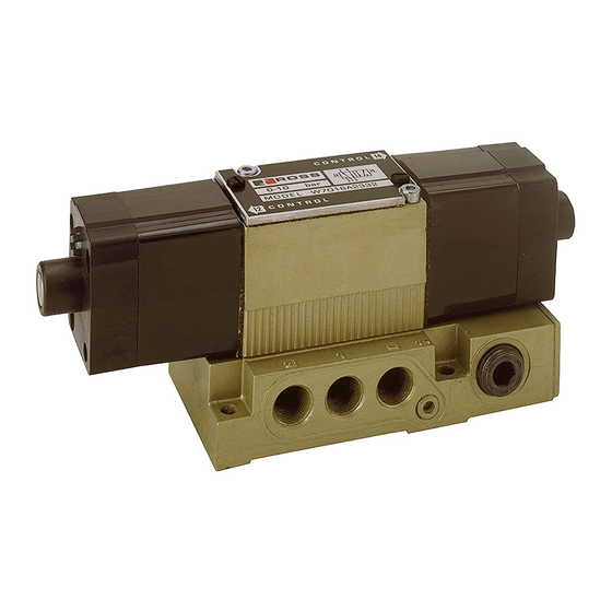
ROSS W70 Series valves and bases
(bases sold separately).
Allowable
rosscontrols.com
Advertisement

Related Manuals for Ross W70 Series


Summary of Contents for Ross W70 Series
- Page 1 Please read and make sure you understand all installation instructions before proceeding with the installation. Additional technical documentation is available for download at rosscontrols.com. If you have any questions about installation or servicing your valve, please contact ROSS or your authorized ROSS distributor, see contact information listed at the back of this document, or visit rosscontrols.com to find your distributor.
- Page 2 Pressure Controlled Valves Media: 40° to 175°F (4° to 80°C) Temperature Ambient/Media: 40° to 175°F (4° to 80°C) Temperature For other temperature ranges, consult ROSS. For other temperature ranges, consult ROSS. Internal or External Pilot Supply Vacuum to 150 psig (10 bar)
- Page 3 Number* Service Kit Seal Kit Gasket Numbe W7016A2331 708K77 — 553B11 171C95 ROSS would be happy to service this valve for you at W7016A2332 709K77 — 553B11 171C95 its factory repair center. If you purchased your valve W7016A3331 276K87 305A87...
- Page 4 ROSS’ obligation under this warranty is limited to repair or replacement of the product or refund of the purchase price paid solely at the discretion of ROSS and provided such product is returned to ROSS freight prepaid and upon examination by ROSS is found to be defective.
Need help?
Do you have a question about the W70 Series and is the answer not in the manual?
Questions and answers