Ross M35 Series Integration Manual
Safety exhaust double valves
Hide thumbs
Also See for M35 Series:
- Operating instructions manual (8 pages) ,
- Operating instructions manual (40 pages)
Table of Contents
Advertisement
Quick Links
Advertisement
Table of Contents

Related Manuals for Ross M35 Series


Summary of Contents for Ross M35 Series
- Page 1 M35 S erieS afety xhauSt ouble alVeS ntegratIon uIde...
-
Page 2: Table Of Contents
Global Locations Disclaimer: Sample Logic and any and all related diagrams contained in ROSS Controls’ Integration guide were developed and validated using dual channel electro-mechanical input signals in a laboratory environment and are provided to you for illustrative purposes only. Because of the many variables and unique requirements associated with any particular application, all persons responsible for installing and integrating ROSS products must satisfy themselves that the ROSS product is the correct product for the application and operates as intended. -
Page 3: Introduction
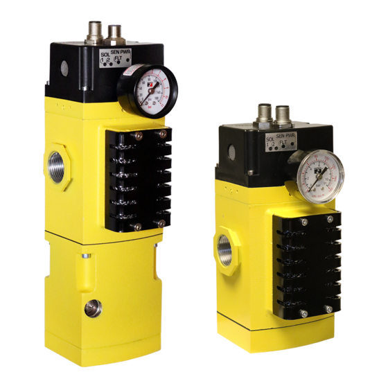
Introduction ROSS Controls offers a variety of safety valves for use in various safety functions such as safe exhaust, safe cylinder return, and safe load holding/stop. This document focuses specifically on ROSS Controls’ M35 Series valves that are used for safe exhaust functions and utilize solid state pressure sensors to provide feedback to a safety control system for external monitoring. -
Page 4: Soft Start Adjustment
115 psig (8 bar) 145 psig (10 bar) Pneumatic Schematic The ROSS M35 valve schematic shows patented cross flow technology and solid state pressure sensors for status feedback. The red box highlights the optional soft-start in the unit. Valve Schematic... -
Page 5: M35 Wiring (Pinouts)
M35 Series Integration Guide M35 Wiring (Pinouts) The M35 valve is available with various wiring options for both the solenoid cable and the sensor cable. For example, the following model number is wired internally with the DB wiring option: Model Number: M35S40GAEXDBGA This means the valve in this example is wired with the D solenoid configuration and the B Sensor configuration. -
Page 6: Operation & Monitoring Requirements For M35 Valves
(as required by the application) regardless of the condition of the feedback sensors. Refer to EN ISO13849-1 for Cat 3 vs Cat 4 monitoring. Automatic RESET is not recommended by ROSS. ROSS CONTROLS © 2021, ®... -
Page 7: Synchronicity
M35 Series Integration Guide Valve Operation and General Feedback Monitoring Ladder Logic Example Safety While Loss Of General Stop Actuate Sensor Sensor Sync. Actuated Pressure Feedback Signal Signal Fault* Fault* Fault* Fault Solenoids Energized < > Solenoid A Solenoids Solenoids <... -
Page 8: While Actuated
M35 Series Integration Guide While Actuated During normal actuation it is possible to see a momentary pressure spike in the sensing area (typically 10 msec duration or less) which causes the sensors to momentarily switch off, then back on before switching off again for the duration of the actuation signal. -
Page 9: M35 Validation Test Procedure For Valve Operation And External Monitoring Logic
M35 Series Integration Guide M35 Validation Test Procedure for Valve Operation and External Monitoring Logic This validation test procedure should only be performed with an M35 valve that is known to be functioning properly. If basic valve function is in NOTE 1: question please refer to Section 8 of the Product Operating Instructions for the Valve Test Procedure. - Page 10 M35 Series Integration Guide Sensor Conditions Actuate Solenoid Outlet Sensor Safety Valve Pass/Fail Port Signal LEDs Pressure Step Action Power System Fault Sensor Sensor Conditions Fault Sol A & Sol B Sol A Sol B Port 2 (P/F) Disconnect sensor output wire from sensor A...
- Page 11 M35 Series Integration Guide Sensor Conditions Actuate Solenoid Outlet Sensor Safety Valve Pass/Fail Port Signal LEDs Pressure Step Action Power System Fault Sensor Sensor Conditions Fault Sol A & Sol B Sol A Sol B Port 2 (P/F) Disconnect sensor output wire from sensor A...
- Page 12 M35 Series Integration Guide Notes ROSS CONTROLS © 2021, ® . All Rights Reserved.
- Page 13 M35 Series Integration Guide Notes www.rosscontrols.com...
- Page 14 M35 Series Integration Guide Notes ROSS CONTROLS © 2021, ® . All Rights Reserved.
-
Page 15: Cautions, Warnings And Standard Warranty
All products are, during their respective warranty periods, warranted to be free of defects in material and workmanship. The ROSS Group’s obligation under this warranty is limited to repair, replacement or refund of the purchase price paid for products which the ROSS Group has determined, in its sole discretion, are defective. - Page 16 Germany manufactIS Tel: +49 (0)2013-16843-0 www.manufactis.net urope ROSS PNEUMATROL www.rossuk.co.uk United Kingdom Tel: +44 (0)1254 872277 (FKA ROSS UK Ltd. and pneumatrol Ltd.) www.pneumatrol.com China ROSS CONTROLS (CHINA) Ltd. Tel: +86-21-6915-7961 www.rosscontrolschina.com & p India ROSS CONTROLS INDIA Pvt. Ltd.
Need help?
Do you have a question about the M35 Series and is the answer not in the manual?
Questions and answers