Table of Contents
Advertisement
Quick Links
Advertisement
Table of Contents

Subscribe to Our Youtube Channel
Related Manuals for EXFO FTB-5230S


Summary of Contents for EXFO FTB-5230S
- Page 1 User Guide FTB-5230S/-OCA Optical Spectrum and Channel Analyzers for FTB-200 v2...
- Page 2 Copyright © 2013 EXFO Inc. All rights reserved. No part of this publication may be reproduced, stored in a retrieval system or transmitted in any form, be it electronically, mechanically, or by any other means such as photocopying, recording or otherwise, without the prior written permission of EXFO Inc.
-
Page 3: Table Of Contents
Contents Certification Information ......................v 1 Introducing the FTB-5230S/-OCA Optical Spectrum and Channel Analyzers ................. 1 Models ............................2 Typical Applications ........................2 Optional Software Packages ....................3 Post-Processing Application ....................3 Conventions ..........................4 2 Safety Information ..................5 3 Getting Started with Your OSA/OCA ............7 Inserting and Removing Test Modules ..................7... - Page 4 Viewing Online Documentation ..................223 Contacting the Technical Support Group ................224 Transportation ........................226 13 Warranty ....................229 General Information ......................229 Liability ..........................230 Exclusions ...........................231 Certification ........................231 Service and Repairs ......................232 EXFO Service Centers Worldwide ..................233 A Technical Specifications ................235 Index .......................237 FTB-5230S/-OCA...
-
Page 5: Certification Information
European Community Declaration of Conformity An electronic version of the declaration of conformity for your product is available on our website at www.exfo.com. Refer to the product’s page on the Web site for details. OSA/OCA... -
Page 7: Introducing The Ftb-5230S/-Oca Optical Spectrum And Channel Analyzers
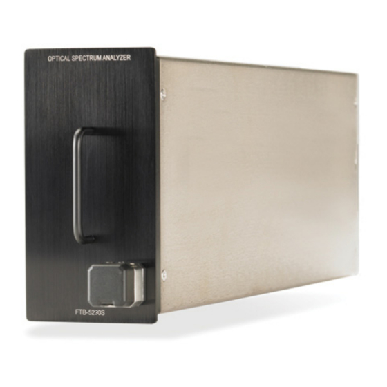
FTB-5230S/-OCA Optical Spectrum and Channel Analyzers The FTB-5230S Optical Spectrum Analyzer (OSA) is designed to measure optical power as a function of wavelength or frequency and Optical Signal to Noise Ratio (OSNR) based on the IEC method (interpolation method). It offers truly portable spectral characterization for DWDM network commissioning. -
Page 8: Models
Models Models The OSA/OCA comes in different models: The FTB-5230S is an entry-level optical spectrum analyzer that is ideal for a variety of field applications, including DWDM and CWDM network commissioning and troubleshooting. The test modes available for your module are WDM and Drift. -
Page 9: Optional Software Packages
Introducing the FTB-5230S/-OCA Optical Spectrum and Channel Analyzers Optional Software Packages Optional Software Packages Optional software options are available for your OCA application. Note: Software options are not available on the OSA. Option Name Description This option enables you to perform full WDM analyses as well as WDM drift measurements, just as you would with an FTB-5230S OSA. -
Page 10: Conventions
Introducing the FTB-5230S/-OCA Optical Spectrum and Channel Analyzers Conventions Conventions Before using the product described in this guide, you should understand the following conventions: ARNING Indicates a potentially hazardous situation which, if not avoided, could result in death or serious injury. Do not proceed unless you understand and meet the required conditions. -
Page 11: Safety Information
Safety Information ARNING Do not install or terminate fibers while a light source is active. Never look directly into a live fiber and ensure that your eyes are protected at all times. ARNING The use of controls, adjustments and procedures other than those specified herein may result in exposure to hazardous situations or impair the protection provided by this unit. - Page 12 Laser Notice No. 50, dated June 24, 2007. Invisible laser radiation may be encountered at the output port. The following label indicates that a product contains a Class 1 source: The maximum input power for the FTB-5230S/-OCA Optical Spectrum and Channel Analyzers is 4 W. For more information on equipment ratings, refer to the user documentation for your platform.
-
Page 13: Getting Started With Your Osa/Oca
AUTION To avoid damaging your unit, use it only with modules approved by EXFO. ARNING When the laser safety LED is flashing, at least one of your modules is emitting an optical signal. Please check all modules, as it might not be the one you are currently using. - Page 14 Getting Started with Your OSA/OCA Inserting and Removing Test Modules To insert a module into the FTB-200 v2: 1. Turn off your unit. 2. Position the unit so that its front panel is facing you. FTB-5230S/-OCA...
- Page 15 Getting Started with Your OSA/OCA Inserting and Removing Test Modules 3. Take the module and place it vertically so that the retaining screw hole is at the left of the connector pins. AUTION Inserting a module upside down could result in permanent damage to the module, as the connector pins might be bent.
- Page 16 This will secure the module into its “seated” position. Turn retaining screws clockwise Bottom panel When you turn on the unit, the startup sequence will automatically detect the module. FTB-5230S/-OCA...
- Page 17 Getting Started with Your OSA/OCA Inserting and Removing Test Modules To remove a module from the FTB-200 v2: 1. Turn off your unit. 2. Position the unit so that the bottom panel is facing you. 3. Lift the mobile part of the retaining screw and use it to turn the retaining screw counterclockwise until it stops.
- Page 18 5. Hold the module by its sides or by the handle (NOT by the connector) and pull it out. AUTION Pulling out a module by a connector could seriously damage both the module and connector. Always pull out a module by its casing. 6. Cover empty slots with the supplied protective covers. FTB-5230S/-OCA...
-
Page 19: Starting Module Applications
Getting Started with Your OSA/OCA Starting Module Applications Starting Module Applications Your modules can be configured and controlled from their dedicated applications in Compact ToolBox. To start a module application: 1. From Compact ToolBox, select the module to use. It will turn blue to indicate that it is highlighted. OSA/OCA... - Page 20 2. Under Applications, select an application, then press Start. To start the Power Meter or Probe application: From Main Menu, press Power Meter or Probe. The main window (shown below) contains all the commands required to control the OSA/OCA: Display panes Function buttons Result panes FTB-5230S FTB-5230S/-OCA...
- Page 21 Getting Started with Your OSA/OCA Starting Module Applications Graph Function buttons Result panes FTB-5230S-OCA Note: The illustrations in this user guide may differ slightly from those on your unit depending on the resolution, application and platform type. OSA/OCA...
-
Page 23: Preparing Your Osa/Oca For A Test
To ensure maximum power and to avoid erroneous readings: Always inspect fiber ends and make sure that they are clean as explained below before inserting them into the port. EXFO is not responsible for damage or errors caused by bad fiber cleaning or handling. - Page 24 EXFO uses good quality connectors in compliance with EIA-455-21A standards. To keep connectors clean and in good condition, EXFO strongly recommends inspecting them with a fiber inspection probe before connecting them. Failure to do so will result in permanent damage to the connectors and degradation in measurements.
-
Page 25: Installing The Exfo Universal Interface (Eui)
Preparing Your OSA/OCA for a Test Installing the EXFO Universal Interface (EUI) Installing the EXFO Universal Interface (EUI) The EUI fixed baseplate is available for connectors with angled (APC) or non-angled (UPC) polishing. A green border around the baseplate indicates that it is for APC-type connectors. -
Page 26: Selecting A Test Mode
Drift: Allows you to monitor an optical link for a fixed duration. Note: You cannot select a test mode in the OCA application. To select a test mode: 1. From the Main Menu, press Mode. FTB-5230S/-OCA... - Page 27 Preparing Your OSA/OCA for a Test Selecting a Test Mode 2. Select the desired test mode. Once you select the mode, you will notice a against the selected mode and all the tabs on the main window and the main menu will change accordingly.
-
Page 28: Nulling Electrical Offsets
Temperature and humidity variations affect the performance of electronic circuits and optical detectors. For this reason, EXFO recommends performing a nulling of the electrical offsets whenever environmental conditions change. - Page 29 Preparing Your OSA/OCA for a Test Nulling Electrical Offsets 2. Disconnect any incoming signal to obtain an optimal accuracy. 3. Press Nulling. You are notified that the nulling is in progress in the status bar. Nulling should be completed in a few seconds. Note: Several features, such as the Start button and Discover, are not available during the nulling process.
-
Page 30: Performing User Calibration
Note: If you want to keep the correction factor list for a later use, save it under a different name in the folder. FTB-5230S/-OCA... - Page 31 Preparing Your OSA/OCA for a Test Performing User Calibration Note: The user calibration feature is not available in the offline version of the OSA/OCA application. To perform a user calibration: 1. Allow your unit to warm up. 2. From the Main Menu, press Analysis Setup. OSA/OCA...
- Page 32 3. Select the Calibration tab. Note: You cannot edit the power or wavelength values directly from the application. The modifications in the user calibration have to be made in a text file, and then it can be loaded in the application. FTB-5230S/-OCA...
- Page 33 Preparing Your OSA/OCA for a Test Performing User Calibration 4. If user correction factors are in the system, press Clear User Correction Factors from Module, then confirm your choice. 5. Take measurements for your test mode. OSA/OCA...
- Page 34 1490.000; 1490.000; 1.09; 1.15 1551.334; 1551.298; -5.20; -5.45 1625.401; 1625.448; 0.00; 0.00 Note: The decimal separator is a point ( . ). This format is independent of the regional settings. 7. Save your .txt file in a location of your choice. FTB-5230S/-OCA...
- Page 35 Preparing Your OSA/OCA for a Test Performing User Calibration 8. Back in the Calibration tab on your unit, load the file using Load Factors. 9. Select the modified user calibration file and press Open. OSA/OCA...
- Page 36 Preparing Your OSA/OCA for a Test Performing User Calibration The calibration values will replace the Correction factors list in the Analysis setup - Calibration window. FTB-5230S/-OCA...
- Page 37 Preparing Your OSA/OCA for a Test Performing User Calibration 10. Press Write to Module to apply the modified calibration values to the module. OSA/OCA...
- Page 38 11. To verify that the calibration changes are properly applied to the module, press Load from Module. Note: The OK and Cancel buttons do not have any impact on the calibration page or the correction factors inside the module. FTB-5230S/-OCA...
- Page 39 Preparing Your OSA/OCA for a Test Performing User Calibration To save a user calibration: 1. From the Main Menu, press Analysis Setup. OSA/OCA...
- Page 40 Preparing Your OSA/OCA for a Test Performing User Calibration 2. Select the Calibration tab. FTB-5230S/-OCA...
- Page 41 Preparing Your OSA/OCA for a Test Performing User Calibration 3. Press Save Factors, to save the modified user calibration values. OSA/OCA...
-
Page 42: Using The Autonaming Feature
Note: The autonaming feature is always active for the OCA application and you can customize it using the trace identification information. Note: The procedure below uses the WDM test mode as an example, but the autonaming feature is available for all test modes. FTB-5230S/-OCA... - Page 43 Preparing Your OSA/OCA for a Test Using the Autonaming Feature To customize the file name: 1. From the Main Menu, press Preferences. OSA/OCA...
- Page 44 Preferences-Information tab. Cable ID: prefix value for the cable ID configured in the Preferences-General tab. Fiber ID: prefix value for the fiber ID configured in the Preferences-General tab. Location description: location description provided in the Preferences-Information tab. FTB-5230S/-OCA...
- Page 45 Preparing Your OSA/OCA for a Test Using the Autonaming Feature 4. Press the up or down arrows to change the order in which the field values will appear in the file name. Based on your selection, a preview of the file name is displayed under File name preview.
- Page 46 To customize the file name in the OCA application: 1. From the main window, select the Trace Info. tab. 2. Press Trace identification. 3. In the General tab, enter the cable ID and fiber ID information you want to use. FTB-5230S/-OCA...
- Page 47 Preparing Your OSA/OCA for a Test Using the Autonaming Feature 4. Select the Use as template option. 5. Press OK to confirm your choice. The new default file name will be “CableID_FiberID_Link###”. If you want to change the word “Link” or the increment number, you can do so in the Save As window, where the information will be kept for the next time you save a file.
-
Page 49: Setting Up The Instrument In Wdm Mode
Setting Up the Instrument in WDM Mode Note: This mode is not available in the OCA application. Before performing a spectral analysis in the WDM mode, you must set up the test application with the appropriate parameters, as explained in this chapter. - Page 50 You can also import the setup from the current trace. This method will take the data and channel information from the current trace and apply them in the corresponding tabs. For more information, see Setting Up WDM Analysis Parameters on page 61. FTB-5230S/-OCA...
-
Page 51: Defining Preferences
Setting Up the Instrument in WDM Mode Defining Preferences Defining Preferences The preferences window allows you to set general information and comments on trace, set display parameters and customize the WDM results table. Note: Only the Display and WDM Results tabs are available in offline mode. Defining Trace Information The trace information relates to the description of the job to be done, cable and job IDs, and any relevant information about what is being tested. - Page 52 2. Select the General tab. 3. Define the general parameters as needed. 4. Press OK to save the changes and close the window, or press Cancel to exit without saving. Press Clear to clear all the changes made in the General tab. FTB-5230S/-OCA...
- Page 53 Setting Up the Instrument in WDM Mode Defining Preferences To enter link and location information: 1. From the Main Menu, press Preferences. 2. Select the Information tab. OSA/OCA...
- Page 54 If the Auto Increment option is not selected, you have to manually change the file name when saving the trace file, otherwise the application will overwrite the previously saved file. Orientation: The orientation of the link. System: Information about the system under test. FTB-5230S/-OCA...
- Page 55 Setting Up the Instrument in WDM Mode Defining Preferences 4. Under Location Information, define the following parameters as needed: Network element: Sets the type of network element. Test point: Sets the location where the test is performed on the ...
- Page 56 Setting Up the Instrument in WDM Mode Defining Preferences To enter comments: 1. From the Main Menu, press Preferences. FTB-5230S/-OCA...
- Page 57 Setting Up the Instrument in WDM Mode Defining Preferences 2. Select the Comments tab. 3. Enter your comments for the current trace. 4. Press OK to save the changes and close the window, or press Cancel to exit without saving. Press Clear to clear all the changes made in the Comments tab.
- Page 58 You can set the spectral unit for the trace and the results table. You can also select the label that should appear on the peaks of the trace. To define display parameters: 1. From the Main Menu, press Preferences. FTB-5230S/-OCA...
- Page 59 Setting Up the Instrument in WDM Mode Defining Preferences 2. Select the Display tab. 3. Select the spectral unit you want to work with, either nm or THz. OSA/OCA...
- Page 60 Setting Up the Instrument in WDM Mode Defining Preferences 4. Select the label that will appear on the peaks in the graph, either the channel name, its number, or nothing. FTB-5230S/-OCA...
- Page 61 Setting Up the Instrument in WDM Mode Defining Preferences Note: The channel name and channel number cannot be shown at the same time. Channel numbers Defined channel names OSA/OCA...
- Page 62 Setting Up the Instrument in WDM Mode Defining Preferences 5. Select whether you want to show or hide the empty channels from the channel list in the Results tab. Note: When selected, empty channels are shown on screen and in the report files. FTB-5230S/-OCA...
- Page 63 Setting Up the Instrument in WDM Mode Defining Preferences 6. Select whether you want to show the horizontal markers or the integrated power and the trace in the marker toolbar. OSA/OCA...
- Page 64 7. Select the background color scheme for the graph as desired. 8. Press OK to save the changes and close the window, or press Cancel to exit without saving. Press Restore Defaults to remove all the changes and apply the default values. FTB-5230S/-OCA...
- Page 65 Setting Up the Instrument in WDM Mode Defining Preferences Customizing WDM Results Table It is possible to select which results you would like to be displayed in the Results tab of your WDM tests. To customize the results table: 1. From the Main Menu, press Preferences. OSA/OCA...
- Page 66 BW 3.00 dB: bandwidth measured by taking the width of a signal at 50 % linear power of the peak, or -3 dB from the peak. BW at x dB: bandwidth measured by taking the width of a signal at x dB from the peak. FTB-5230S/-OCA...
-
Page 67: Setting Up Wdm Analysis Parameters
Setting Up the Instrument in WDM Mode Setting Up WDM Analysis Parameters /f : deviation of the spectral center of mass for the peak in that channel. /f Peak: spectral peak in that channel. /f Peak: deviation of the spectral peak in that channel. ... - Page 68 Setting Up the Instrument in WDM Mode Setting Up WDM Analysis Parameters To import the parameters from the current trace: 1. Make sure that you have a trace on-screen. 2. From the Main Menu, press Analysis Setup. FTB-5230S/-OCA...
- Page 69 Setting Up the Instrument in WDM Mode Setting Up WDM Analysis Parameters 3. From any tab, press Import from Trace. 4. Press OK to confirm the changes. OSA/OCA...
- Page 70 In the General tab, you can set the default channel parameters. Any channel found during an acquisition that is not defined in the channel list will be analyzed according to the default channel settings. To define general settings: 1. From the Main Menu, press Analysis Setup. FTB-5230S/-OCA...
- Page 71 Setting Up the Instrument in WDM Mode Setting Up WDM Analysis Parameters 2. Select the General tab. OSA/OCA...
- Page 72 Clear the Activate default channel option to use the currently defined channel list for analysis. This reduces the analysis time by eliminating the peak detection over the complete spectral range. The peaks outside the defined channel list will not be analyzed. FTB-5230S/-OCA...
- Page 73 Setting Up the Instrument in WDM Mode Setting Up WDM Analysis Parameters Channel width (GHz or nm): indicates the limit inside which the power values will be considered in the channel. For default channels, the channel width that sets the limits of the channel, should be the same as the channel distance or smaller (channel distance is defined while creating a channel list).
- Page 74 OSA will approximate the noise curve using a fifth order polynomial fit. This fit definition relies on fit and exclusion zones. Only the points in the fit zones are used to calculate the fifth order polynomial fit. If you select the fifth order polyfit method, you have FTB-5230S/-OCA...
- Page 75 Setting Up the Instrument in WDM Mode Setting Up WDM Analysis Parameters to define the fit and exclusion zones for your tests using the OSNR distance and noise region fields. The exclusion zone is indirectly obtained from the OSNR distance. Channel width Exclusion zone...
- Page 76 OSA/OCAs having different effective resolutions. The instrument’s RBW value is written below the graph. This parameter does not actually have an effect on the acquisition, but is only a normalization factor used to provide the OSNR value in a standardized manner. FTB-5230S/-OCA...
- Page 77 Power offset (dB): indicates the offset value applied on the power. This does not replace a calibration performed at EXFO, but it can help you achieve the specifications if you have determined that, for example, your modules are used beyond the normal allowed use.
- Page 78 Global Results tab (See Global Results Tab on page 184). When thresholds are globally disabled, results are displayed without a Pass/Fail status and the Global pass/fail status will not be active in the Global Results tab. The P/F column under the results table will not be displayed. FTB-5230S/-OCA...
- Page 79 Setting Up the Instrument in WDM Mode Setting Up WDM Analysis Parameters You can set your pass/fail threshold limits in different ways depending on the type of test you are performing. Threshold Limit Definition None No threshold limit is set. The results will be displayed without a Pass/Fail verdict.
- Page 80 Setting Up the Instrument in WDM Mode Setting Up WDM Analysis Parameters To define global thresholds: 1. From the Main Menu, press Analysis Setup. 2. Select the Global Thresholds tab. FTB-5230S/-OCA...
- Page 81 Setting Up the Instrument in WDM Mode Setting Up WDM Analysis Parameters 3. Select the Activate all thresholds option to manually set the global threshold values. If this option is not selected, all the thresholds will be deactivated, results are displayed without a Pass/Fail status and Global pass/fail status are not active in the Global Results tab.
- Page 82 Default thresholds will be applied to any channel found outside the channel list during the acquisition or re-analysis. Note: The default thresholds settings are enabled only when the Activate all thresholds option is selected in the Global Thresholds tab. For more information, see Defining Global Thresholds on page 72. FTB-5230S/-OCA...
- Page 83 Setting Up the Instrument in WDM Mode Setting Up WDM Analysis Parameters You can set your pass/fail threshold limits in different ways depending on the type of test you are performing. Threshold Limit Definition None No threshold limit is set. The results will be displayed without a Pass/Fail verdict.
- Page 84 Setting Up the Instrument in WDM Mode Setting Up WDM Analysis Parameters To define default Thresholds: 1. From the Main Menu, press Analysis Setup. FTB-5230S/-OCA...
- Page 85 Setting Up the Instrument in WDM Mode Setting Up WDM Analysis Parameters 2. Select the Default Thresholds tab. 3. Enter values in the boxes as explained below: Wavelength/Frequency (nm/GHz): the channel’s central wavelength/frequency. Signal power (dBm): the signal power for the default channel ...
- Page 86 1.2 GHz (approximately) of frequency range is common between the two channels. To add a channel list: 1. From the Main Menu, press Analysis Setup. FTB-5230S/-OCA...
- Page 87 Setting Up the Instrument in WDM Mode Setting Up WDM Analysis Parameters 2. Select the Channels tab. 3. By default, the channel list is empty. Press Add Channels. OSA/OCA...
- Page 88 Channel width (nm or GHz): limit inside which the power values will be considered in the channel. Integrated power is calculated on channel width. Name prefix: adds a prefix to the channel names. FTB-5230S/-OCA...
- Page 89 Setting Up the Instrument in WDM Mode Setting Up WDM Analysis Parameters Starting value: sets the increment starting value for the channel name in the channel list. Increment value: sets the increment value for the channel name in the channel list.
- Page 90 Setting Up the Instrument in WDM Mode Setting Up WDM Analysis Parameters To edit the parameters of a specific channel: 1. From the Main Menu, press Analysis Setup. FTB-5230S/-OCA...
- Page 91 Setting Up the Instrument in WDM Mode Setting Up WDM Analysis Parameters 2. Select the Channels tab. 3. Select the channel or channels to be modified in the channel list. If you want the changes to be applied to all of your channels, press Select All.
- Page 92 Setting Up the Instrument in WDM Mode Setting Up WDM Analysis Parameters 4. Press Edit Selection. FTB-5230S/-OCA...
- Page 93 Setting Up the Instrument in WDM Mode Setting Up WDM Analysis Parameters 5. Modify the settings as needed. For more information about the settings, see Defining General Settings on page 64 and Defining Default Thresholds on page 76. If you leave a box empty, it will remain as it was before your changes.
-
Page 94: Setting Up Acquisition Parameters
Before performing measurements on an optical spectrum, you must select the wavelength/frequency range to use. You can perform the scan on the full range, on spectral bands, or select a custom range. Note: The shorter the wavelength or frequency range, the faster the acquisition. FTB-5230S/-OCA... - Page 95 Setting Up the Instrument in WDM Mode Setting Up Acquisition Parameters To set parameters in the Acquisition tab: 1. From the main window, select the Acquisition tab. 2. Select the acquisition type. OSA/OCA...
- Page 96 E band (extended): 1355 to 1465 nm S band (short wavelengths): 1455 to 1535 nm C band (conventional “erbium window”): 1525 to 1570 nm L band (long wavelengths): 1560 to 1630 nm U band (ultralong wavelengths): 1620 to 1650 nm. FTB-5230S/-OCA...
-
Page 97: Setting Up The Instrument In Drift Mode
Setting Up the Instrument in Drift Mode Note: This mode is not available in the OCA application. Before performing a spectral analysis in the Drift mode, you must set up the test application with the appropriate parameters, as explained in this chapter. - Page 98 You can also import the setup from the current trace. This method will take the data and channel information from the current trace and apply them in the corresponding tabs. For more information, see Setting Up Drift Analysis Parameters on page 107. FTB-5230S/-OCA...
-
Page 99: Defining Preferences
Setting Up the Instrument in Drift Mode Defining Preferences Defining Preferences The preferences window allows you to set general information and comments on trace, set display parameters and customize the drift results table. Note: Only the Display and Drift Results tabs are available in offline mode. Defining Trace Information The trace information relates to the description of the job to be done, cable and job IDs, and any relevant information about what is being tested. - Page 100 2. Select the General tab. 3. Define the general parameters as needed. 4. Press OK to save the changes and close the window, or press Cancel to exit without saving. Press Clear to clear all the changes made in the General tab. FTB-5230S/-OCA...
- Page 101 Setting Up the Instrument in Drift Mode Defining Preferences To enter link and location information: 1. From the Main Menu, press Preferences. 2. Select the Information tab. OSA/OCA...
- Page 102 Description: Enter the description of location if required. 5. Press OK to save the changes and close the window, or press Cancel to exit without saving. Press Restore Defaults to remove all the changes and apply the default values. FTB-5230S/-OCA...
- Page 103 Setting Up the Instrument in Drift Mode Defining Preferences To enter comments: 1. From the Main Menu, press Preferences. OSA/OCA...
- Page 104 2. Select the Comments tab. 3. Enter your comments for the current trace. 4. Press OK to save the changes and close the window, or press Cancel to exit without saving. Press Clear to clear all the changes made in the Comments tab. FTB-5230S/-OCA...
- Page 105 Setting Up the Instrument in Drift Mode Defining Preferences Defining Display Parameters The application allows you to set display settings for the acquisition trace. You can set the spectral unit for the trace and the results table. You can also select the label that should appear on the peaks of the trace.
- Page 106 Setting Up the Instrument in Drift Mode Defining Preferences 2. Select the Display tab. 3. Select the spectral unit you want to work with, either nm or THz. FTB-5230S/-OCA...
- Page 107 Setting Up the Instrument in Drift Mode Defining Preferences 4. Select the label that will appear on the peaks in the graph, either the channel name, its number, or nothing. OSA/OCA...
- Page 108 Setting Up the Instrument in Drift Mode Defining Preferences Note: The channel name and channel number cannot be shown at the same time. Channel numbers Defined channel names FTB-5230S/-OCA...
- Page 109 Setting Up the Instrument in Drift Mode Defining Preferences 5. Select whether you want to show or hide the empty channels from the channel list in the Dashboard, Channel Graph, Channel Results and Channel History tabs. 6. Select whether you want to show the horizontal markers or the integrated power trace in the marker toolbar.
- Page 110 7. Select the background color scheme for the graph as desired. 8. Press OK to save the changes and close the window, or press Cancel to exit without saving. Press Restore Defaults to remove all the changes and apply the default values. FTB-5230S/-OCA...
- Page 111 Setting Up the Instrument in Drift Mode Defining Preferences Customizing Drift Results Table It is possible to select which results you would like to be displayed in the Results tab of your Drift tests. To customize the results table: 1. From the Main Menu, press Preferences. OSA/OCA...
- Page 112 Noise (according to the current calculation method, in dBm). 4. Press OK to save the changes and close the window, or press Cancel to exit without saving. Press Restore Defaults to remove all the changes and apply the default values. FTB-5230S/-OCA...
-
Page 113: Setting Up Drift Analysis Parameters
Setting Up the Instrument in Drift Mode Setting Up Drift Analysis Parameters Setting Up Drift Analysis Parameters This section presents the various analysis settings for the application, particularly the channel list and settings. These settings are applied on subsequent acquisitions. You can set the channel list, global thresholds, default channel thresholds, channel parameters, manage favorite configurations and perform user calibration. - Page 114 Setting Up the Instrument in Drift Mode Setting Up Drift Analysis Parameters 3. From any tab, press Import from Trace. 4. Press OK to confirm the changes. FTB-5230S/-OCA...
- Page 115 Setting Up the Instrument in Drift Mode Setting Up Drift Analysis Parameters Defining General Settings The general analysis parameters for drift acquisitions affect the calculation of the results. These calculations take place after an acquisition. If these settings are modified, they will be applied to the next acquisition. MPORTANT In the General tab, you can set the default channel parameters.
- Page 116 Setting Up the Instrument in Drift Mode Setting Up Drift Analysis Parameters 2. Select the General tab. FTB-5230S/-OCA...
- Page 117 Setting Up the Instrument in Drift Mode Setting Up Drift Analysis Parameters 3. Under Default channel settings, define the following parameters as needed: Clear the Activate default channel selection, to use the currently defined channel for analysis. This reduces the analysis time by eliminating the peak detection over the complete spectral range.
- Page 118 In some cases, for instance CATV signals, signals with high-frequency modulation, or signals with an inherent line width similar or larger than the OSA/OCA's resolution bandwidth, this calculation becomes a better estimation of the true signal power. FTB-5230S/-OCA...
- Page 119 Setting Up the Instrument in Drift Mode Setting Up Drift Analysis Parameters Peak signal power: The peak signal power represents the maximum power value inside the channel. Note that it differs a little from the peak measurement on the spectrum due to the fact that the estimated noise is subtracted to get the peak signal power.
- Page 120 It is independent of the channel width. Noise region: The noise region, or fit zone, defines the region where the polynomial fit applies. Two identical regions are centered at the OSNR distance. FTB-5230S/-OCA...
- Page 121 Setting Up the Instrument in Drift Mode Setting Up Drift Analysis Parameters 4. Under Global analysis parameters, define the following parameters as needed: Peak detection level (dBm): indicates the minimum power level from where the peak can be considered as a signal. RBW for OSNR (nm): indicates the resolution bandwidth selected ...
- Page 122 Power offset (dB): indicates the offset value applied on the power. This does not replace a calibration performed at EXFO, but it can help you achieve the specifications if you have determined that, for example, your modules are used beyond the normal allowed use.
- Page 123 Setting Up the Instrument in Drift Mode Setting Up Drift Analysis Parameters Defining Default Channel Thresholds The thresholds will be applied to any channel found outside the channel list during the next acquisition. Thresholds will be applied to the channel results during the next acquisition.
- Page 124 Setting Up the Instrument in Drift Mode Setting Up Drift Analysis Parameters When thresholds are globally disabled, the results in the Channel Results tab are also displayed without a Pass/Fail status. FTB-5230S/-OCA...
- Page 125 Setting Up the Instrument in Drift Mode Setting Up Drift Analysis Parameters You can set your pass/fail threshold limits in different ways depending on the type of test you are performing. Threshold Limit Definition None No threshold limit is set. The results will be displayed without a Pass/Fail verdict.
- Page 126 Setting Up the Instrument in Drift Mode Setting Up Drift Analysis Parameters To define the default channel thresholds: 1. From the Main Menu, press Analysis Setup. FTB-5230S/-OCA...
- Page 127 Setting Up the Instrument in Drift Mode Setting Up Drift Analysis Parameters 2. Select the Thresholds tab. OSA/OCA...
- Page 128 3. Select the Activate all thresholds option to manually set the channel threshold values. If this option is not selected, all the thresholds will be deactivated, results are displayed without a Pass/Fail status in the Channel Graph, Channel History and Channel Results tabs. FTB-5230S/-OCA...
- Page 129 Setting Up the Instrument in Drift Mode Setting Up Drift Analysis Parameters 4. Enter values in the boxes as explained below: Wavelength/Frequency (nm/GHz): central wavelength/frequency of the channel. Signal power (dBm): signal power for the selected channel (excludes noise). OSNR (dB): Optical Signal to Noise Ratio, given by Signal power ...
- Page 130 1.2 GHz (approximately) of frequency range is common between the two channels. To add a channel list: 1. From the Main Menu, press Analysis Setup. FTB-5230S/-OCA...
- Page 131 Setting Up the Instrument in Drift Mode Setting Up Drift Analysis Parameters 2. Select the Channels tab. 3. By default, the channel list is empty. Press Add Channels. OSA/OCA...
- Page 132 Channel center wavelength/frequency: spectral center-of-mass for the peak in that channel. Note: When using the custom channel center wavelength option, the first channel will be centered at the Start Range, and the list will be created using channel distance and channel width. FTB-5230S/-OCA...
- Page 133 Setting Up the Instrument in Drift Mode Setting Up Drift Analysis Parameters Channel distance (nm or GHz): distance between the channels. The value of channel distance will be set depending on the selection made for the channel center wavelength option. The channel distance box will be enabled only when the channel center wavelength option is set to custom.
- Page 134 Setting Up the Instrument in Drift Mode Setting Up Drift Analysis Parameters To edit the parameters of a specific channel: 1. From the Main Menu, press Analysis Setup. FTB-5230S/-OCA...
- Page 135 Setting Up the Instrument in Drift Mode Setting Up Drift Analysis Parameters 2. Select the Channels tab. OSA/OCA...
- Page 136 If you want the changes to be applied to all of your channels, press Select All. Channels can be selected one by one or all together. You can press Unselect All to clear all channel selections. To delete the selected channels, press Delete. 4. Press Edit Selection. FTB-5230S/-OCA...
- Page 137 Setting Up the Instrument in Drift Mode Setting Up Drift Analysis Parameters 5. Modify the settings as needed. For more information about the settings, see Managing Channels on page 124. If you leave a box empty, it will remain as it was before your changes. Modify appropriate settings. 6.
-
Page 138: Setting Up Acquisition Parameters
You can configure the delay, sampling and total duration for a drift measurement. You can also configure the drift files name and select a location where it should be saved. The application allows you to perform a trial scan while setting up the drift measurement. FTB-5230S/-OCA... - Page 139 Setting Up the Instrument in Drift Mode Setting Up Acquisition Parameters To set parameters in the Acquisition tab: 1. From the main window, select the Acquisition tab. OSA/OCA...
- Page 140 To select the wavelength range using the double slider, move the left and right handles on the double slider or simply click on any band. Note: You can select more than one adjoining ranges to include in your range, for example, S + C. FTB-5230S/-OCA...
- Page 141 Setting Up the Instrument in Drift Mode Setting Up Acquisition Parameters The wavelength range covered within these bands of the spectra are listed below. O band (original): 1255 to 1365 nm E band (extended): 1355 to 1465 nm S band (short wavelengths): 1455 to 1535 nm ...
- Page 142 4. Select a duration unit and enter a duration count to configure the total duration of a drift measurement. 5. Enter a drift file name that should be used to save the drift file. Note: This is not available in offline mode. FTB-5230S/-OCA...
- Page 143 Setting Up the Instrument in Drift Mode Setting Up Acquisition Parameters 6. Select a location where the drift file should be saved. 7. Select whether you want to keep all of the historical traces in the subfolder, keep only the significant ones, or keep none. The historical traces are stored in separate *.osawdm files.
- Page 144 WDM Graph tab and Channel Results tab. The Channel History tab displays results as if only time 0:00 was available. The other drift mode tabs are empty (Dashboard, Channel Graph). FTB-5230S/-OCA...
-
Page 145: Building A Custom Drift Measurement
Setting Up the Instrument in Drift Mode Building a Custom Drift Measurement Building a Custom Drift Measurement You can build a drift measurement using a WDM measurement you already have as a reference. The selected channels and thresholds can be imported from the analysis setup or the reference measurement. - Page 146 Instrument’s serial Target WDM measurement Compatible number instrument’s serial number differs with warnings from drift reference trace instrument’s serial number Instrument’s RBW Target WDM measurement Compatible instrument’s RBW differs from drift with warnings reference trace instrument’s RBW FTB-5230S/-OCA...
- Page 147 Setting Up the Instrument in Drift Mode Building a Custom Drift Measurement Compatibility Criteria Test Status Power offset Target WDM measurement power Compatible offset differs from drift reference with warnings trace power offset Wavelength offset Target WDM measurement Compatible wavelength offset differs from drift with warnings reference trace wavelength offset Noise measurement Target WDM measurement...
- Page 148 To build a custom drift measurement: 1. If you have not done so already, select the Drift test mode. 2. From the main window, select Custom Build. 3. Select the reference trace you want to use to build the measurement, then click Next. FTB-5230S/-OCA...
- Page 149 Setting Up the Instrument in Drift Mode Building a Custom Drift Measurement 4. Select whether you want to import the analysis setup from the selected reference file, or use the settings currently set in your application, then click Next. OSA/OCA...
- Page 150 Setting Up the Instrument in Drift Mode Building a Custom Drift Measurement 5. Enter, or review if they were imported, the general details for your measurement. See Defining General Settings on page 109 for details on each item. 6. Click Next. FTB-5230S/-OCA...
- Page 151 Setting Up the Instrument in Drift Mode Building a Custom Drift Measurement 7. If desired, adjust the threshold settings for your measurement. For details on each item, see Defining Default Channel Thresholds on page 117. When you are done, click Next. OSA/OCA...
- Page 152 Setting Up the Instrument in Drift Mode Building a Custom Drift Measurement 8. Select which channels are to be included in the drift measurement. For details on each item, see Managing Channels on page 124. When you are done, click Next. FTB-5230S/-OCA...
- Page 153 Setting Up the Instrument in Drift Mode Building a Custom Drift Measurement 9. Add one or more measurement files at this point, then click Next. OSA/OCA...
- Page 154 (keep them all, keep only the significant ones, or keep none), set the drift file name and its location. 11. Once you are ready, click Build. Once the process is complete, you can navigate through the results of the built drift. FTB-5230S/-OCA...
-
Page 155: Setting Up Your Oca
Setting Up Your OCA Performing a spectral analysis with your Optical Channel Analyzer (OCA) is simple and can be achieved after selecting a few parameters. Before performing your test, you must set the acquisition type and channel plan. Your OCA features two types of acquisitions: Single: Spectral measurement is performed once. - Page 156 Setting Up Your OCA To set parameters in the Acquisition tab: 1. From the main window, select the Acquisition tab. 2. Select the acquisition type. 3. Select the channel plan to use. FTB-5230S/-OCA...
- Page 157 Setting Up Your OCA To create a channel plan and use it as one of the Custom channel plans: 1. Start the post-processing application on a computer, and select the WDM test mode. 2. From the Main Menu, select Analysis Setup. 3.
- Page 158 Custom file if needed. Note: If you want to modify an existing Custom channel plan, make a copy of it in Windows Explorer, and rename it with the .osawdmsetup extension before importing it in the Favorites tab of the OSA post-processing application. FTB-5230S/-OCA...
-
Page 159: Starting A Measurement
Starting a Measurement Before starting a measurement you must select and configure a test mode. You will find the instructions to select a test mode in Selecting a Test Mode on page 20. For instructions on configuring various test modes, see their respective sections. -
Page 161: Managing Files And Test Configurations
Managing Files and Test Configurations Using the Discover Feature The Discover feature allows you to start a measurement procedure to automatically build an analysis setup (scan range, channel list, analysis parameters, etc.) based on the signal being detected on the input port of the module. - Page 162 ITU grids (25, 50, 100 or 200 GHz). If your channel is not based on the ITU grid, the results may not be correct. In this case, you can use the default channel definition or create a new channel list. FTB-5230S/-OCA...
- Page 163 Managing Files and Test Configurations Using the Discover Feature To start an automatic setup measurement: Note: You cannot do a setup measurement in offline mode. From the Main Menu, press Discover. The Start button turns into a Stop button and the first scan of the discover starts. Note: If you already have an active trace on screen that was modified, you will be prompted to save it.
-
Page 164: Managing Measurement Files
2. If desired, change the location and file name. 3. Press Save to save the trace, else press Cancel to exit the window. Note: Once a trace is overwritten, you cannot access it anymore. Note: You cannot save a reference trace. FTB-5230S/-OCA... - Page 165 Managing Files and Test Configurations Managing Measurement Files To open a file: 1. From the Main Menu, Press File, and then press Open (for the OCA application, there is no File menu). From the main window, press 2. If you had already acquired (but not saved) a trace, a warning window appears, asking you if you want to save the current trace.
- Page 166 5. Press Open to open the file. The trace appears in the Graph tab. All the values in the main window will also be updated from the file. FTB-5230S/-OCA...
- Page 167 Managing Files and Test Configurations Managing Measurement Files To clear a file: 1. From the Main Menu, Press File. (for the OCA application, skip step 1) 2. Press New. 3. If you had already acquired (but not saved) a trace, a warning window appears, asking you if you want to save the current trace.
-
Page 168: Opening Other Test Mode Files In Wdm Mode
If an Input trace is present in the file, it is imported as the WDM reference trace. If an Output trace is present in the file, it is imported as the WDM active trace. FTB-5230S/-OCA... -
Page 169: Managing Favorites
Managing Files and Test Configurations Managing Favorites Managing Favorites Favorites are configuration files that contain all of the parameters from the Analysis Setup tab and Acquisition tab. When you often use the same settings, you can save them as a favorite, then recall them for future acquisitions. - Page 170 Managing Files and Test Configurations Managing Favorites 2. Select the Favorites tab. FTB-5230S/-OCA...
- Page 171 Managing Files and Test Configurations Managing Favorites 3. To apply the settings from a favorite file to the current analysis setup, select a file from the favorites list and press Apply Selection. This button will be enabled only when a file is selected from the favorites list.
- Page 172 Managing Files and Test Configurations Managing Favorites To save a test configuration: 1. From the Main Menu, press Analysis Setup. From the main window, press FTB-5230S/-OCA...
- Page 173 Managing Files and Test Configurations Managing Favorites 2. Select the Favorites tab. 3. To save an analysis setup to a file, press Save As. The default folder where the file will be saved is the Favorites folder. You should use this folder unless you want to transfer a copy on an external storing device such as a USB stick.
- Page 174 Analysis Setup – Favorites tab. 5. Press Save to save the configuration and close the window, or press Cancel to exit without saving. To import a test configuration: 1. From the Main Menu, press Analysis Setup. From the main window, press FTB-5230S/-OCA...
- Page 175 Managing Files and Test Configurations Managing Favorites 2. Select the Favorites tab. 3. Press Import to import an analysis setup from a file. OSA/OCA...
- Page 176 Favorites tab. 5. Press OK to load the configuration and close the window, or press Cancel to exit without saving. Note: To load this newly imported test configuration, you must select it from the favorites list and press Apply Selection. FTB-5230S/-OCA...
- Page 177 Managing Files and Test Configurations Managing Favorites To delete a test configuration: 1. From the Main Menu, press Analysis Setup. From the main window, press OSA/OCA...
- Page 178 Managing Files and Test Configurations Managing Favorites 2. Select the Favorites tab. FTB-5230S/-OCA...
-
Page 179: Importing A Configuration From The Current Trace
Managing Files and Test Configurations Importing a Configuration from the Current Trace 3. To delete a configuration file from the favorites list, select it and press Delete. Press Yes to confirm your choice. Importing a Configuration from the Current Trace In the OSA application, you can import the analysis and channel configuration from the measurement file currently on-screen.See Setting Up WDM Analysis Parameters on page 61 for details. -
Page 181: 10 Managing Results
The polarization scrambler inside the module could be defective. If you suspect this option please contact EXFO technical support for a more complete diagnosis. Polynomial fit coefficient correlation is questionable. -
Page 182: Managing Wdm Test Results
Graph Tab The Graph tab allows you to view the spectrum of the active and reference traces. This graph represents the optical power against wavelength or frequency. FTB-5230S/-OCA... - Page 183 Managing Results Managing WDM Test Results When the acquisition is taken (see Starting a Measurement on page 153 for details on how to perform a test), the active trace will be displayed in the tab with information along the following axis values: X axis: wavelength in nm or frequency in THz.
- Page 184 Note: This is valid only for channels in the list for which a signal is detected. If you select a channel that has no signal, no peak is selected in the graph. FTB-5230S/-OCA...
- Page 185 Managing Results Managing WDM Test Results The noise level for a channel is indicated by a dotted line under the selected peak. The width of the noise level indicator is set according to the current Noise for OSNR setting. The width of the noise level indicator depends on the noise associated with the OSNR setting (from the largest to the narrowest): IEC, InB, InB nf and fit.
- Page 186 Note: If there is a reference trace, it appears in gray in the graph. Note: For more information on these, see Managing Markers on page 206 and Using Zoom Controls on page 204. FTB-5230S/-OCA...
- Page 187 Managing Results Managing WDM Test Results Results Tab In the Results tab, each channel will be represented for both the active and reference traces, with the delta between both results. Only the results for the channels within the scan range will be analyzed. The pass ( )/fail ) verdict for thresholds are also displayed;...
- Page 188 If the verdict is fail for any parameter, its value will appear in red. If the verdict is pass, its value will appear in green. To view channel results: 1. From the main window, select Channel Results tab. FTB-5230S/-OCA...
- Page 189 Managing Results Managing WDM Test Results 2. Select a row from the Results tab to view the results for this channel. Note: Values displayed in the Channel Result tabs are those of the active trace only. Note: For details on each result type, see Customizing WDM Results Table on page 59 and Defining General Settings on page 64.
- Page 190 Analysis Setup window. If the thresholds are enabled, the Pass/Fail status pane will display a Pass or Fail status based on the global results, or Not Active if the thresholds are disabled. Note: Values displayed in the Global Results tab are indicated for the active trace only. FTB-5230S/-OCA...
-
Page 191: Managing Drift Test Results
Managing Results Managing Drift Test Results Managing Drift Test Results The application allows you to view and manage your drift test results. You can view the dashboard, channel graph and WDM graph of your drift acquisition, channel history results for a single channel and information about the trace. - Page 192 Both the current pass/fail status (last completed acquisition) and the historical pass/fail status are displayed in the dashboard. The historical pass/fail status will be set to Fail as soon as one occurrence of fail has occurred in the past or in the current acquisition. FTB-5230S/-OCA...
- Page 193 Managing Results Managing Drift Test Results The dashboard shows a global status (all channels) for each parameter. This global status is set to Fail if at least one channel has a failed historical status for that given parameter, otherwise the global status is set to Pass. OSA/OCA...
- Page 194 The dashboard displays a channel status (all parameters) for a given channel. This channel status is set to Fail as soon as one of the parameters has a failed historical status for that given channel, otherwise the channel status is set to Pass. FTB-5230S/-OCA...
- Page 195 Managing Results Managing Drift Test Results Channel Graph Tab The Channel Graph tab displays three different graphs for the selected channel. You can select which graphs you want to display from the Drift Results tab in the Preferences Window. The three graphs are X-Y plots of: Spectral position (center of mass of wavelength or frequency) of the ...
- Page 196 Channel History table: Spectral position (center of mass of wavelength or frequency) of the channel against time (nm or THz) Signal power of the channel against time (dBM) OSNR of the channel against time (dB) FTB-5230S/-OCA...
- Page 197 Managing Results Managing Drift Test Results For each of the above parameters, the following results are displayed: Reference: channel reference values for the current drift acquired during the initial acquisition. Current Drift: current drift values, that is, the current deviation from the ...
- Page 198 Managing Drift Test Results WDM Graph Tab The WDM Graph tab allows you to view the spectrum of the active trace for the last WDM acquisition in your drift measurement. This graph represents the optical power versus wavelength or frequency. FTB-5230S/-OCA...
- Page 199 Managing Results Managing Drift Test Results When the acquisition is taken (see Starting a Measurement on page 153 for details on how to perform a test), the active trace will be displayed in the tab with information along the following axis values: X axis: wavelength in nm or frequency in THz.
- Page 200 Channel Results tab. If the verdict is fail for any parameter, its value appears in red. If the verdict is pass, its value appears in green. To view channel results: 1. From the main window, select Channel Results tab. FTB-5230S/-OCA...
- Page 201 Managing Results Managing Drift Test Results 2. Select a channel from the Channel History tab to view the channel results for the selected channel. Note: For details on each item, see Customizing WDM Results Table on page 59 and Defining General Settings on page 64. OSA/OCA...
-
Page 202: Managing Oca Test Results
Note: Viewing and modifying existing OCA measurement files is only possible with the module application; there is no post-processing application for this type of measurement. Graph The graph allows you to view the spectrum of the trace. This graph represents the optical power against wavelength. FTB-5230S/-OCA... - Page 203 Managing Results Managing OCA Test Results When the acquisition is taken (see Starting a Measurement on page 153 for details on how to perform a test), the trace will be displayed in the graph with information along the following axis values: X axis: wavelength in nm.
- Page 204 In the graph zone, you can change the selected peak by clicking inside the peak limits of the desired channel. Peak selection in the graph is synchronized with the channel selection in lower tab results list; changing the selection in the graph modifies the selection in the list and vice-versa. FTB-5230S/-OCA...
- Page 205 Managing Results Managing OCA Test Results The graph will also display a dotted line across the full spectral width corresponding to the peak detection level indicator. This line indicates the minimum power level (dBm) from where a peak can be considered as a valid signal.
- Page 206 The results table shows the current channel results for the trace and the total power in the scan range. Empty channel results will not be displayed in the channel list. To view results: From the main window, select the Results tab. FTB-5230S/-OCA...
-
Page 207: Adjusting The Display Size
Managing Results Adjusting the Display Size Adjusting the Display Size Your application allows you to toggle the view of your main window. You can change the view of the upper and lower tabs from the normal view to 100 % upper tabs or 100 % lower tabs view. To adjust the display size: For 100 % upper tabs view, press OSA/OCA... - Page 208 Managing Results Adjusting the Display Size For 100 % lower tabs view, press FTB-5230S/-OCA...
-
Page 209: Viewing Wdm Graph In Full-Screen Mode
Managing Results Viewing WDM Graph in Full-Screen Mode Viewing WDM Graph in Full-Screen Mode The full-screen mode allows you to see the WDM graph, including the markers, using the whole screen of your unit. It also displays three lines of results. -
Page 210: Using Zoom Controls
Note: You cannot select channels on the graph when the markers are displayed. Selection mode Move view area Zoom in on the defined area Full view Zoom in Zoom out Auto zoom on peak (not available in the OCA application) Note: You can only move the markers with the button. FTB-5230S/-OCA... - Page 211 Managing Results Using Zoom Controls To view specific portions of the graph: You can define which portion of the graph will be visible by pressing and dragging the graph with the stylus or your finger. You can also zoom in on a specific area by pressing and defining ...
-
Page 212: Managing Markers
Note: If you select a vertical marker while the horizontal markers are active, the selection will toggle to the other type of marker and vice versa. Note: If you zoom into the graph, or pan within it, the markers remain in their set positions. FTB-5230S/-OCA... - Page 213 Managing Results Managing Markers You can also use the automated marker positioning to place the markers around a specific channel peak. The positions are set from the results grid, according to the following by default: A: set at the peak wavelength “ Peak(nm)” or frequency “ƒ ...
- Page 214 integrated power between the markers in dBm (when horizontal markers are hidden) power difference between the traces (active against reference or input against output) for both markers in dB (when horizontal markers are hidden). FTB-5230S/-OCA...
- Page 215 Managing Results Managing Markers As markers C and D appear on the graph, the power difference between the markers (C-D) related to the horizontal markers will be displayed in the marker toolbar. You can also move the markers directly on the graph tab. Drag the marker to the desired area in the display.
-
Page 216: Managing Trace Information
Use as template option and press OK. To view trace information parameters: 1. From the main window, select the Trace Info. tab. 2. For some test types (if there is a reference trace), select which trace you want to view. FTB-5230S/-OCA... - Page 217 Managing Results Managing Trace Information To edit general information: 1. From the main window, select the Trace Info. tab. 2. Press Trace Identification. Note: Trace identification is not available for the WDM reference trace. 3. Select the General tab. 4. Edit the general information as required. 5.
- Page 218 3. Select the Information tab. 4. Edit the information as required. 5. Press OK to save the changes and close the window, or press Cancel to exit without saving. Press Restore Defaults to remove all the changes and apply the default values. FTB-5230S/-OCA...
- Page 219 Managing Results Managing Trace Information To edit comments: Note: This feature is not available in the OCA application. 1. From the main window, select the Trace Info. tab. 2. Press Trace Identification. 3. Select the Comments tab. 4. Edit comments in the Comments window for the current trace. 5.
-
Page 220: Generating Reports
Note: Empty channels that are shown on screen are included in the report files. To generate a report: 1. From the Main Menu, select File (for the OCA application, skip step 1). 2. Press Report. 3. In the Save As window, enter a file name. FTB-5230S/-OCA... - Page 221 Managing Results Generating Reports 4. From the Save as type list, select the format for your report. 5. Press Save. The report will be added to the Reports folder. You can change the location where you want to save the report as desired. OSA/OCA...
-
Page 223: 11 Maintenance
11 Maintenance To help ensure long, trouble-free operation: Always inspect fiber-optic connectors before using them and clean them if necessary. Keep the unit free of dust. Clean the unit casing and front panel with a cloth slightly dampened ... - Page 224 Maintenance Cleaning EUI Connectors ARNING Looking into the optical connector while the light source is active WILL result in permanent eye damage. EXFO strongly recommends to TURN OFF the unit before proceeding with the cleaning procedure. To clean EUI connectors: 1.
- Page 225 6d. Verify connector surface with a portable fiber-optic microscope (for example, EXFO’s FOMS) or fiber inspection probe (for example, EXFO’s FIP). 7. Put the EUI back onto the instrument (push and turn clockwise).
-
Page 226: Recalibrating The Unit
Under normal use, the recommended interval for your FTB-5230S/-OCA Optical Spectrum and Channel Analyzers is: one year. For newly delivered units, EXFO has determined that the storage of this product for up to six months between calibration and shipment does not affect its performance (EXFO Policy PL-03). -
Page 227: Recycling And Disposal (Applies To European Union Only)
To ensure that your unit conforms to the published specifications, calibration may be carried out at an EXFO service center or, depending on the product, at one of EXFO’s certified service centers. Calibrations at EXFO are performed using standards traceable to national metrology institutes. -
Page 229: 12 Troubleshooting
12 Troubleshooting Viewing Online Documentation An online version of the FTB-5230S/-OCA Optical Spectrum and Channel Analyzers user guide is available at all times from the application. Note: You will also find a printable PDF version on your installation DVD. To access online help:... -
Page 230: Contacting The Technical Support Group
Contacting the Technical Support Group To obtain after-sales service or technical support for this product, contact EXFO at one of the following numbers. The Technical Support Group is available to take your calls from Monday to Friday, 8:00 a.m. to 7:00 p.m. - Page 231 Troubleshooting Contacting the Technical Support Group To view the information about the product: From the Main Menu, press OSA/OCA...
-
Page 232: Transportation
AUTION Always use the GP-10-055 case when transporting the FTB-5230S module. EXFO does not recommend transporting the modules in a platform and/or in a case other than the one designed for your specific module. Handle the case with care when transporting the module. - Page 233 Troubleshooting Transportation The following image show the GP-10-055 case with the module inside. Module OSA/OCA...
-
Page 235: 13 Warranty
13 Warranty General Information EXFO Inc. (EXFO) warrants this equipment against defects in material and workmanship for a period of one year from the date of original shipment. EXFO also warrants that this equipment will meet applicable specifications under normal use. -
Page 236: Liability
Liability Liability EXFO shall not be liable for damages resulting from the use of the product, nor shall be responsible for any failure in the performance of other items to which the product is connected or the operation of any system of which the product may be a part. -
Page 237: Exclusions
Warranty Exclusions Exclusions EXFO reserves the right to make changes in the design or construction of any of its products at any time without incurring obligation to make any changes whatsoever on units purchased. Accessories, including but not limited to fuses, pilot lamps, batteries and universal interfaces (EUI) used with EXFO products are not covered by this warranty. -
Page 238: Service And Repairs
5. Return the equipment, prepaid, to the address given to you by support personnel. Be sure to write the RMA number on the shipping slip. EXFO will refuse and return any package that does not bear an RMA number. -
Page 239: Exfo Service Centers Worldwide
Warranty EXFO Service Centers Worldwide EXFO Service Centers Worldwide If your product requires servicing, contact your nearest authorized service center. EXFO Headquarters Service Center 400 Godin Avenue 1 866 683-0155 (USA and Canada) Quebec (Quebec) G1M 2K2 Tel.: 1 418 683-5498... -
Page 241: A Technical Specifications
From 1520 to 1600 nm. g. Over one minute in continuous acquisition mode. c. For FTB-5230S only. After user calibration in the same test session within 10 nm from each h. At 1550 nm, -10 dBm input. calibration point. -
Page 243: Index
Index Index center frequency......... 60, 79, 106 acquisition wavelength ......60, 79, 106 averaging........88, 132 certification information........ v real-time ........88, 149 channel single ........88, 132, 149 center, wavelength or frequency ... 82, 126 type ............38 count, empty ......... 75 activating increment value ........ - Page 244 ......... 19 identification label........224 dust cap..........19 importing analysis setup......168 EUI connectors, cleaning ......217 increment channel value...... 83, 127 EXFO universal interface. see EUI information link and location ........47 system under test ........96 FTB-5230S/-OCA...
- Page 245 Index inserting a module ........7 module integrated power ........ 67, 112 detection ..........10 ITU grid ..........67, 112 insertion........... 7 removal............ 7 mounting EUI connector adapter ....19 label, identification ........224 level noise ........... 79 link name ID............
- Page 246 ID ............ 96 analysis ..........155 name ..........82, 127 importing..........168 preparing OSA for a test ......17 shipping to EXFO........232 product signal power..........68 identification label....... 224 average ..........75 specifications ........235 calculation ........67, 112 channel ......
- Page 247 Index flatness ..........75 trace peak............. 113 clearing ..........161 signal to noise ratio......69, 114 managing ..........158 single acquisition mode ....88, 132, 149 opening ..........159 snap to ITU grid ........67, 112 saving ..........158 software packages ........3 transportation requirements....
- Page 248 Index analysis parameters ....... 61 general settings ........64 opening files in other formats ..... 162 results, customizing......105 setting up mode ........43 test results ........... 176 width,channels...... 67, 82, 112, 127 zoom controls ........... 204 FTB-5230S/-OCA...
- Page 249 CHINESE REGULATION ON RESTRICTION OF HAZARDOUS SUBSTANCES NAMES AND CONTENTS OF THE TOXIC OR HAZARDOUS SUBSTANCES OR ELEMENTS CONTAINED IN THIS EXFO PRODUCT EXFO Indicates that this toxic or hazardous substance contained in all of the homogeneous materials for this part is below the limit requirement in SJ/T11363-2006...
- Page 250 MARKING REQUIREMENTS Product Environmental protection use period (years) Logo This Exfo product EXFO Battery If applicable.
- Page 251 Tel.: 1 978 367-5600 · Fax: 1 978 367-5700 EXFO FINLAND Elektroniikkatie 2 FI-90590 Oulu, FINLAND Tel.: +358 (0) 403 010 300 · Fax: +358 (0) 8 564 5203 TOLL-FREE (USA and Canada) 1 800 663-3936 © 2013 EXFO Inc. All rights reserved. Printed in Canada (2013-11) ...
Need help?
Do you have a question about the FTB-5230S and is the answer not in the manual?
Questions and answers