Table of Contents

Related Manuals for AMX DMS


Summary of Contents for AMX DMS
- Page 1 Operation/Reference Guide Mio Modero DMS & Mio Modero DMS Pinnacle D o c u m e n t I D : 0 4 1 - 0 0 4 - 2 9 6 0 C o n t r o l S y s t e m A c c e s s o r i e s...
- Page 2 RMA number. AMX is not liable for any damages caused by its products or for the failure of its products to perform. This includes any lost profits, lost savings, incidental damages, or consequential damages. AMX is not liable for any claim made by a third party or by an AMX Dealer for a third party.
- Page 3 AMX's entire liability and Licensee's exclusive remedy shall be repair or replacement of the AMX Software that does not meet AMX's Limited Warranty and which is returned to AMX. This Limited Warranty is void if failure of the AMX Software has resulted from accident, abuse, or misapplication.
-
Page 5: Table Of Contents
Standard Mounting Procedures for Non-metallic Units ... 9 Installing the Mio Modero DMS using expansion clips... 9 Installing the Mio Modero DMS into a flat surface using mounting screws... 12 Removing the device from the wall... 13 Standard Mounting Procedures for Metallic Units..13 Expansion Clip Installation of the Conduit Box ... - Page 6 Sending Firmware to The Mio Modero DMS and DMS Pinnacle Keypads ... 52 Before beginning the Upgrade process ... 52 Upgrading The Mio Modero DMS And Mio Modero DMS Pinnacle Firmware via An IP Ad- dress ... 53 Preparing the Master for communication via an IP... 53 Verifying and Upgrading the device firmware via an IP ...
-
Page 7: Overview
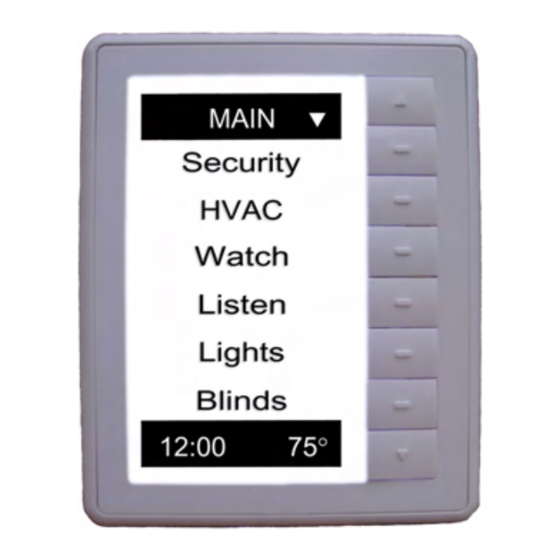
Overview The Mio Modero DMS and DMS Pinnacle device family provides a wide range of control capabilities in the form of user specified touch keypads that are functional yet recherché. The devices are available as follows: Mio Modero DMS and DMS Pinnacle Device Family Mio Modero DMS Mio Modero DMS Pinnacle An LCD touch-selection keypad with touch slider navigation. -
Page 8: Specifications
Included Accessories: Other AMX Equipment: Available Color Schemes The Mio Modero DMS and DMS Pinnacle device family is available in a range of colors, and supports a variety of Lutron color schemes. Mio Modero DMS and DMS Pinnacle Color Schemes... -
Page 9: Dynamic Menu System
The Mio Modero DMS Pushbutton Feature The Mio Modero DMS is equipped with a 8 pushbuttons that allows you to navigate and select within the dynamic menu system displayed in the LCD overlay area. The top and bottom buttons serve as Up and Down navigation for your menu system. -
Page 10: Mio Modero Dms Conduit Box
Mio Modero DMS Conduit Box Overview The Mio Modero DMS Conduit Box is available with the metallic paint version of the DMS and DMS Pinnacle. Additionally, the rest of the Mio Modero DMS product family can be fitted with this conduit box. -
Page 11: Installation
DMS Pinnacle. After you have completed the installation you must consult Necessary Device Setup section on page 20. Rear Components The rear components of the Mio Modero DMS and DMS Pinnacle (FIG. 2 non-metallic, FIG. 3 metallic) are the same for both devices: Ethernet Port (PoE) 2-pin 3.5 mm mini-Phoenix... - Page 12 Installation FIG. 3 Mio Modero DMS and DMS Pinnacle Rear Components Ethernet Port (PoE) Magnetic Posts 2-pin 3.5 mm mini-Phoenix (female) connector metallic unit Mio Modero DMS & Mio Modero DMS Pinnacle (Front View)
-
Page 13: Front Components
Sections of The Mio Modero DMS and DMS Pinnacle Wiring With the Mio Modero DMS and DMS Pinnacle, you can use either a 12 VDC power or CAT5/CAT6 wire to the Ethernet port for PoE power. Do not connect power to the Mio Modero DMS and DMS Pinnacle until the wiring is complete. -
Page 14: Using The Psn Netlinx Connector For Power
Orange 3 --------- 3 3 --------- 6 White-Green 4 --------- 4 Blue 5 --------- 5 White-Blue 6 --------- 6 Green 7 --------- 7 White-Brown 8 --------- 8 Brown Mio Modero DMS & Mio Modero DMS Pinnacle 12 VDC Power Supply... -
Page 15: Standard Mounting Procedures For Non-Metallic Units
1. If assembled, remove the Mio Modero DMS from the conduit box. Place a flathead screwdriver between the tab of the conduit box and the notch of the Mio Modero DMS (see FIG. 2) and pop the two apart. Pull the bottom of the unit out (pivoting on the top clip) until it seems to bind against the shielding;... - Page 16 Expansion Clip Installation Point 5. Insert the conduit box and expansion clips into the cutout until the rim of the conduit box is flush against the wall. Mio Modero DMS Mio Modero DMS & Mio Modero DMS Pinnacle Drywall Expansion Clips...
- Page 17 7. Connect the 2-pin power connector and/or CAT5 cables in the back of the Mio Modero DMS. See FIG. 2 for port locations. 8. Insert and fasten the Mio Modero DMS into the conduit box, start at the top of the device and tilt in toward the bottom.
-
Page 18: Installing The Mio Modero Dms Into A Flat Surface Using Mounting Screws
1. If assembled, remove the Mio Modero DMS from the conduit box. Place a flathead screwdriver between the tab of the conduit box and the notch of the Mio Modero DMS (see FIG. 2) and pop the two apart. Pull the bottom of the unit out (pivoting on the top clip) until it seems to bind against the shielding;... -
Page 19: Removing The Device From The Wall
6. Connect the 2-pin power connector and/or CAT5 cables in the back of the Mio Modero DMS. See FIG. 2 for port locations. 7. Insert and fasten the Mio Modero DMS into the conduit box, start at the top of the device and tilt in toward the bottom. -
Page 20: Rough-In Installation Of The Conduit Box
8. Connect the 2-pin power connector and/or CAT5/CAT6 cables in the back of the Mio DMS. See FIG. 3 for port locations. 9. Insert the Mio DMS into the conduit box. You will feel the magnets grab the side of the conduit box, push until the device is flush to the wall. -
Page 21: Installing The Conduit Box Without The Use Of Tabs
6. Connect the 2-pin power connector and/or CAT5/CAT6 cables in the back of the Mio DMS. See FIG. 3 for port locations. 7. Insert the Mio DMS into the conduit box. You will feel the magnets grab the side of the conduit box, push until the device is flush to the wall. -
Page 22: Mounting The Magnetic Post Housing On A Mio Modero Dms
1. If in the wall, remove the Mio Modero DMS from the conduit box. Place a flathead screwdriver between the tab of the conduit box and the notch of the Mio Modero DMS and pop the two apart. Pull the bottom of the unit out (pivoting on the top clip) until it seems to bind against the shielding;... - Page 23 FIG. 15 Rear and side view of magnetic housing 7. Insert the provided cardboard paint shield into the conduit box if the Mio Modero DMS will not be installed at this time. Mio Modero DMS & Mio Modero DMS Pinnacle...
- Page 24 Installation Mio Modero DMS & Mio Modero DMS Pinnacle...
-
Page 25: Device Setup
Device Setup The Mio Modero DMS and Mio Modero DMS Pinnacle are equipped with setup pages that allow you to set and configure various features of the devices. Some menu items are compulsory, Necessary Device Setup section on page 20, while other items are optional, Optional Device Setup section on page 33. -
Page 26: Accessing The Setup Page
Device Setup Accessing the Setup Page If you have not loaded any pages on your Mio Modero DMS device, it will launch the Setup page by default. Otherwise, do one of the following to access the Setup page: Mio Modero DMS - Press and hold down the Up and Down buttons for 3 seconds. -
Page 27: Ip Settings - Mio Modero Dms
IP Settings - Mio Modero DMS The configuration of the Mio Modero DMS and Mio Modero DMS Pinnacle requires you set the communication protocol. Your options are either Static or DHCP. From the Setup page, follow these steps: 1. Push the button that corresponds to Protected Setup. If you do not have a password established, the device will not prompt you for one. - Page 28 •Done accepts changes and returns to the previous page. After you have set your Host Name and pressed Done, press Return to finalize your changes and go back to the IP Settings page. Mio Modero DMS & Mio Modero DMS Pinnacle...
- Page 29 IP Address Required Subnet Mask Mio Modero DMS & Mio Modero DMS Pinnacle Press the button that corresponds to IP Address. To change the IP address from what is listed, press the button next to the IP Address to enter the edit page.
- Page 30 •Done accepts changes and returns to the previous page. After you have set your Host Name and pressed Done, press Return to finalize your changes and go back to the IP Settings page. Mio Modero DMS & Mio Modero DMS Pinnacle...
-
Page 31: Ip Settings - Mio Modero Dms Pinnacle
If you selected Static you must set the following in the IP Settings: Static Required IP Address Mio Modero DMS & Mio Modero DMS Pinnacle Select More... Select Host Name. If the Host Name is different than localhost, select localhost to enter the edit page. - Page 32 •Done accepts changes and returns to the previous page. After you have set your Host Name and selected Done, select Return to finalize your changes and go back to the IP Settings page. Mio Modero DMS & Mio Modero DMS Pinnacle...
-
Page 33: Master Connection - Mio Modero Dms
Master Connection - Mio Modero DMS The Mio Modero DMS and Mio Modero DMS Pinnacle require you establish the type of connection you want made between it and the NetLinx master. From the Setup page, follow these steps: 1. Push the button that corresponds to Protected Setup. If you do not have a password established, the device will not prompt you for one. - Page 34 From the Setup page, select the button next to Protected Setup. If you do not have a password established on the Mio Modero DMS Pinnacle, the device will not prompt you for one. The default password is 1988. See the Set Protected Password section on page 33 for more information.
- Page 35 12. After you have set your Password and pressed Done, press Return to finalize your changes and go back to the Master Connection page. 13. The DMS keypad must be rebooted to store communication changes. Mio Modero DMS & Mio Modero DMS Pinnacle...
-
Page 36: Master Connection - Mio Modero Dms Pinnacle
Confirm device IP is on the Master URL list. You can set the Host Name on the device and use it to locate the device on the master. Host Name is particularly useful in the DHCP scenario where the IP address can change. Mio Modero DMS & Mio Modero DMS Pinnacle... - Page 37 Setting the Friendly Name: From the Setup page, select Protected Setup. If you do not have a password established on the Mio Modero DMS Pinnacle, the device will not prompt you for one. The default password is 1988. See the Set Protected Password section on page 33 for more information.
- Page 38 12. After you have set your Password and selected Done, select Return to finalize your changes and go back to the Master Connection page. 13. The DMS keypad must be rebooted to store communication changes. Mio Modero DMS & Mio Modero DMS Pinnacle...
-
Page 39: New Terms
The device multicasts until it is discovered and bound to a master. Optional Device Setup If you have not loaded any pages on your Mio Modero DMS device, it will launch the Setup page by default. Otherwise, do one of the following to access the Setup page: Mio Modero DMS - Press and hold down the Up and Down buttons for 3 seconds. -
Page 40: Remove User Pages
2. Select Other Settings. 3. Select Remove User Pages. 4. Select Yes to confirm. Keypad Info The Keypad Info page provides read-only information for the Mio Modero DMS and Mio Modero DMS Pinnacle. FIG. 20 Keypad Info Mio Modero DMS - Press the button that correlates to your menu selection to view the information. -
Page 41: Time / Date
The Time / Date page is populated by the master. FIG. 21 Time Adjust Mio Modero DMS - Press the button that correlates to your menu selection to view the information. Mio Modero DMS Pinnacle - Select the menu item to view the information. -
Page 42: Display Settings
FIG. 22 Display Settings Mio Modero DMS - Press the button that correlates to your menu selection to set the value. Mio Modero DMS Pinnacle - Select the menu item to set the value. Display Settings Menu... - Page 43 Pinnacle). To change the Timeout from what is listed, press the button next to the Screen Saver Timeout (Mio Modero DMS) or select Screen Saver Timeout (Mio Modero DMS Pinnacle) to enter the edit page. •The Up and Down buttons scroll through numerals. (Mio Modero...
-
Page 44: Audio Settings
The Audio Settings page allows you to set the volume, mute and device feedback on the device. FIG. 23 Audio Settings Mio Modero DMS - Press the button that correlates to your menu selection to set the value. Mio Modero DMS Pinnacle - Select the menu item to set the value. Audio Settings... -
Page 45: Programming The Mio Modero Dms And Dms Pinnacle
Recognized SEND_COMMANDs Below is a list of SEND_COMMANDs accepted by the Mio Modero DMS and Mio Modero DMS Pinnacle device family from NetLinx masters. To use these commands, establish a Telnet session from the PC to the NetLinx master. Additionally, you could use NetLinx Studio 2.4 or the master’s web page to send the commands. -
Page 46: Button Commands
Programming The Mio Modero DMS and DMS Pinnacle "^" Button Commands These Button Commands are used in the NetLinx protocol and are case insensitive. All commands that begin with "^" have the capability of assigning a variable text address range and button state range. - Page 47 Example: SEND_COMMAND Keypad,"'^SHO-500.504&510.515,0'" Hides buttons with variable text address range 500-504 & 510-515. Mio Modero DMS & Mio Modero DMS Pinnacle Programming The Mio Modero DMS and DMS Pinnacle Stan[dardPage] - Flip to standard page Prev[iousPage] - Flip to previous page...
- Page 48 Programming The Mio Modero DMS and DMS Pinnacle "^" Button Commands (Cont.) Sets Non-Unicode text. ^TXT Assign a text Syntax: string to those buttons with a Variables: defined address range. • variable text address range = 1 - 4000. • button states range = 1 - 2 (1 = Off state, 2 = On state).
-
Page 49: Keypad Runtime Commands
Sends the keypad to the Setup Page. Syntax: SLEEP Force the keypad "'SLEEP'" into screen saver Example: mode. SEND COMMAND Keypad,"'SLEEP'" Turns backlight off. Mio Modero DMS & Mio Modero DMS Pinnacle Programming The Mio Modero DMS and DMS Pinnacle... - Page 50 Programming The Mio Modero DMS and DMS Pinnacle Keypad Runtime Commands (Cont.) This command turns On page tracking, whereby when the page or popups change, a TPAGEON string is sent to the Master. This string may be captured with a CREATE_BUFFER Turn On page command for one keypad and sent directly to another keypad.
-
Page 51: Listboxes
KeypadBuilder to create both static and dynamic commands. List Box Commands The Mio Modero DMS and Mio Modero DMS Pinnacle support Data List Box Commands. List Box Commands Data List Commands ^LDN Creates a new data list. - Page 52 Programming The Mio Modero DMS and DMS Pinnacle List Box Commands (Cont.) Data List Commands ^LDA Adds a new row to an existing data list. Primary data is required. List box commands contain comma-delimited fields, but you can use commas within the fields.
- Page 53 ^LDC Clears all rows in a given list. ^LDD Deletes the data list. Mio Modero DMS & Mio Modero DMS Pinnacle Programming The Mio Modero DMS and DMS Pinnacle Syntax: "'^LDR-<list address>,<uniflag>,<primary data>'" Variables: • list address = address where data resides •...
- Page 54 Programming The Mio Modero DMS and DMS Pinnacle List Box Commands (Cont.) Data List Commands ^LDT Sets the column type for a data list. Column is the index of the first type to set, additional types sent are set in order.
- Page 55 Data list; set the data list displayed. ^LVP Set position; display a new position. Mio Modero DMS & Mio Modero DMS Pinnacle Programming The Mio Modero DMS and DMS Pinnacle Syntax: "'^LVO-<view address>,<sort>'" Variables: • view address = the address of the view definition •...
- Page 56 Programming The Mio Modero DMS and DMS Pinnacle List Box Commands (Cont.) Command Structure List View ^LVM Move; display a new position. ^LVS Sort; sets column order for sorting. Update must be called for changes to take effect. ^LVC Column display order; sets the table column each view column displays.
- Page 57 "’^LDA-1,0,8,The Shins,Chutes Too Narrow,Turn a Square,"10,8"’" "’^LDA-1,0,9,The Shins,Chutes Too Narrow,Gone for Good,"10,9"’" "’^LDA-1,0,10,The Shins,Chutes Too Narrow,Those to Come,"10,10"’" "’^LVC-2,4’" "’^LVU-2’" Mio Modero DMS & Mio Modero DMS Pinnacle Programming The Mio Modero DMS and DMS Pinnacle Syntax: "'^LVU-<view address>'" Variables: •...
-
Page 58: Sending Firmware To The Mio Modero Dms And Dms Pinnacle Keypads
If power or connection fails during a firmware upgrade, the file system may become corrupted. A Mio Modero DMS or Mio Modero DMS Pinnacle which is not using a valid username and password will not communicate with a secured Master. If you are updating the firmware on a keypad which is not using a username or password field, you must first remove the Master Security feature to establish an unsecured connection. -
Page 59: Upgrading The Mio Modero Dms And Mio Modero Dms Pinnacle Firmware Via An Ip Address
NetLinx Master instruction manual to use an address. Note the IP Address and Gateway information. 2. Launch NetLinx Studio 2.4 (default location is Start > Programs > AMX Control Disc > NetLinx Studio > NetLinx Studio 2.4). -
Page 60: Verifying And Upgrading The Device Firmware Via An Ip
3. After the Communication Verification dialog window verifies active communication between the PC and the Master, verify the Mio Modero DMS or Mio Modero DMS Pinnacle appears in the OnLine Tree tab of the Workspace window. The default device value is 10001. - Page 61 Master (listed in the OnLine Tree tab of the Workspace window). The Port field is greyed-out. 8. Click the Reboot Device checkbox. This causes the Mio Modero DMS or Mio Modero DMS Pinnacle device to reboot after the firmware update process is complete.
- Page 62 It’s Your World - Take Control™ 3000 RESEARCH DRIVE, RICHARDSON, TX 75082 USA • 800.222.0193 • 469.624.8000 • 469-624-7153 fax • 800.932.6993 technical support • www.amx.com...
Need help?
Do you have a question about the DMS and is the answer not in the manual?
Questions and answers