Sign In
Upload
Manuals
Brands
ITT Manuals
Water Pump
Goulds Pumps XHD
ITT Goulds Pumps XHD Manuals
Manuals and User Guides for ITT Goulds Pumps XHD. We have
3
ITT Goulds Pumps XHD manuals available for free PDF download: Installation, Operation And Maintenance Manual
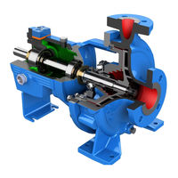
ITT Goulds Pumps XHD Installation, Operation And Maintenance Manual (160 pages)
Brand:
ITT
| Category:
Water Pump
| Size: 12 MB
Table of Contents
Table of Contents
3
Introduction and Safety
6
Introduction
6
Safety
7
Safety Terminology and Symbols
7
Environmental Safety
8
User Safety
9
Safety Regulations for Ex-Approved Products in Potentially Explosive Atmospheres
10
Product Approval Standards
12
Product Warranty
13
Transportation and Storage
14
Inspect the Delivery
14
Inspect the Package
14
Inspect the Unit
14
Transportation Guidelines
14
Pump Handling
14
Lifting Methods
14
Storage Guidelines
16
Pump Storage Requirements
17
Frostproofing
17
Product Description
18
General Description I-ALERT
18
Equipment Health Monitor
18
Nameplate Information
18
Installation
21
Pre-Installation
21
Pump Location Guidelines
21
Foundation Requirements
22
Baseplate-Mounting Procedures
23
Prepare the Baseplate for Mounting
23
Install the Baseplate Using Shims or Wedges
23
Install the Baseplate Using Jackscrews
24
Direct-Coupled Baseplate-Leveling Worksheet
27
Install Pump, Driver, and V-Belt Drive
28
Install and Align the Sheaves
28
Install and Tension the Belt
28
Install the Pump, Driver, and Coupling
29
Pump-To-Driver Alignment
29
Alignment Checks
29
Permitted Indicator Values for Alignment Checks
30
Alignment Measurement Guidelines
30
Attach the Dial Indicators for Alignment
31
Pump-To-Driver Alignment Instructions
31
Grout the Baseplate
34
Piping Checklists
35
General Piping Checklist
35
Suction-Piping Checklist
37
Discharge Piping Checklist
39
Bypass-Piping Considerations
40
Auxiliary-Piping Checklist
41
Final Piping Checklist
41
Commissioning, Startup, Operation, and Shutdown
42
Commissioning, Startup, Operation, Andshutdown
42
Preparation for Startup
42
Remove the V-Belt Drive Guard
43
Remove the Coupling Guard
43
Check the Rotation - Frame Mounted
44
Impeller-Clearance Check
45
Impeller Axial Clearances
45
Impeller-Clearance Setting
45
Set Impeller to Suction Seal Ring Clearance Dial Indicator Method
47
Set Impeller Clearance Dial Indicator Method - XHD
50
Suction Seal Ring Clearance Check - XHD Only
51
Install the V-Belt Drive Guard
52
V-Belt Drive Operation
52
Belt Drive Installation Checks
52
V-Belt Drive Monitoring and Protection
53
Couple the Pump and Driver
53
Install the Coupling Guard
55
Bearing Lubrication
57
Lubricate the Bearings with Oil
57
Shaft-Sealing Options
58
Mechanical Seal Options
58
Connection of Sealing Liquid for Mechanical Seals
58
Packed Stuffing Box Option
59
Connection of Sealing Liquid for a Packed Stuffing Box
59
Seal the Shaft with a Packed Stuffing Box
59
Pump Priming
62
Prime the Pump with the Suction Supply above the Pump
62
Prime the Pump with the Suction Supply below the Pump
63
Other Methods of Priming the Pump
65
Start the Pump
65
Activate the I-ALERT Health Monitor
66
I-ALERT ® 2 Equipment Health Monitor
67
Pump Operation Precautions
67
Shut down the Pump
68
Deactivate the I-ALERT ® 2 Equipment Health Monitor
68
Reset the I-ALERT ® 2 Health Monitor
68
Make the Final Alignment of the Pump and Driver
70
Maintenance
71
Maintenance Schedule
71
Bearing Maintenance
72
Lubricating Oil Requirements
72
Oil Volumes
73
Acceptable Oil for Lubricating Bearings
73
Lubricating-Grease Requirements
74
Shaft-Seal Maintenance
75
Disassembly
78
Disassembly Precautions
78
Wet End Disassembly Instructions
78
Tools Required
78
Disassembly for Metal-Lined
79
Typical Disassembly - Metal-Lined
79
Complete Wet End Disconnection - XHD Only
79
Wet End Disassembly Instructions
80
Disassembly for Rubber-Lined
91
Disassembly - Rubber-Lined
91
Remove the Joint Gaskets and Flanges - Rubber-Lined
91
Remove the Suction Half Casing - Rubber-Lined
92
Remove the Remaining Suction Half Components - Rubber-Lined
93
Remove Suction Side Liner - XHD Single Piece Suction Liner - Rubber-Lined
93
Impeller Removal - Rubber-Lined
94
Stuffing Box Removal
96
Remove the Split Stuffing Box XHD
96
Remove the Casing Volute Liner - Rubber-Lined
96
Remove the Power End - Quick Disconnect Option for XHD
98
Remove the Expeller (Optional Feature)
99
Remove the Seal Cover and Gland Half Casing Assembly
100
Optional Disassembly of Gland Half Casing, Gland Liner, and Seal Cover - Rubber-Lined
100
Locate and Lift the Volute Liner for Optional Discharge Locations (Field Replacement) - Rubber-Lined
101
Remove the Shaft Sleeve
102
Remove the Power End- XHD and XHD Value Option
103
Disassemble the Power End - XHD, Oil Lubrication
105
Disassembly of Other Power End Configurations
108
Preassembly Inspections
109
Replacement Guidelines
109
Power End Inspection
110
Reassembly
110
Assemble the Power End- XHD, Oil Lubrication
110
Assemble the Power End to the Pedestal
113
Assembly of Other Power End Configurations
115
Wet End Assembly Instructions
116
Complete Wet End Connection - XHD
116
Wet End Assembly Instructions
117
Assembly References
131
Troubleshooting
140
Operation Troubleshooting
140
Alignment Troubleshooting
141
Assembly Troubleshooting
141
I-ALERT ® 2 Equipment Health Monitor Troubleshooting
141
Parts Listings and Cross-Sectionals
142
Assembly Drawings - (Exploded Views)
142
Certification: CE or CE ATEX
152
Certificates of Conformance
152
Other Relevant Documentation or Manuals
158
Local ITT Contacts
159
Regional Offices
159
Advertisement
ITT Goulds Pumps XHD Installation, Operation And Maintenance Manual (155 pages)
Brand:
ITT
| Category:
Water Pump
| Size: 15 MB
Table of Contents
Table of Contents
3
1 Introduction and Safety
7
Introduction
7
Requesting Other Information
7
Safety
7
Safety Terminology and Symbols
8
Environmental Safety
9
User Safety
9
Safety Regulations for Ex-Approved Products in Potentially Explosive Atmospheres
11
Product Approval Standards
13
ATEX Considerations and Intended Use
14
Product Warranty
15
2 Transportation and Storage
16
Inspect the Delivery
16
Inspect the Package
16
Inspect the Unit
16
Transportation Guidelines
16
Precautions
16
Pump Handling
16
Lifting Methods
16
Storage Guidelines
18
Storage Location
18
Pump Storage Requirements
18
Frostproofing
18
3 Product Description
19
General Description I-ALERT®2 Equipment Condition Monitor
19
Nameplate Information
19
4 Installation
22
Pre-Installation
22
Pump Location Guidelines
22
Foundation Requirements
23
Baseplate-Mounting Procedures
24
Prepare the Baseplate for Mounting
24
Install the Baseplate Using Shims or Wedges
24
Install the Baseplate Using Jackscrews
25
Direct-Coupled Baseplate-Leveling Worksheet
29
Install Pump, Driver, and V-Belt Drive
30
Install and Align the Sheaves
30
Install and Tension the Belt
30
Install the Pump, Driver, and Coupling
31
Pump-To-Driver Alignment
31
Alignment Checks
32
Permitted Indicator Values for Alignment Checks
32
Alignment Measurement Guidelines
33
Attach the Dial Indicators for Alignment
33
Pump-To-Driver Alignment Instructions
33
Grout the Baseplate
36
Piping Checklists
38
General Piping Checklist
38
Suction-Piping Checklist
39
Discharge Piping Checklist
42
Bypass-Piping Considerations
43
Auxiliary-Piping Checklist
44
Final Piping Checklist
44
5 Commissioning, Startup, Operation, and Shutdown
45
Preparation for Startup
45
Remove the V-Belt Drive Guard
46
Remove the Coupling Guard
47
Check the Rotation
48
Impeller-Clearance Check
49
Impeller Axial Clearances
49
Impeller-Clearance Setting
49
Set Impeller to Suction Seal Ring Clearance Dial Indicator Method
50
Set Impeller Clearance Dial Indicator Method - XHD
53
Suction Seal Ring Clearance Check - XHD Only
54
Install the V-Belt Drive Guard
55
V-Belt Drive Operation
56
Belt Drive Installation Checks
56
V-Belt Drive Monitoring and Protection
56
Couple the Pump and Driver
57
Install the Coupling Guard
58
Bearing Lubrication
61
Lubricate the Bearings with Oil
62
Shaft-Sealing Options
62
Mechanical Seal Options
63
Connection of Sealing Liquid for Mechanical Seals
63
Packed Stuffing Box Option
63
Connection of Sealing Liquid for a Packed Stuffing Box
63
Seal the Shaft with a Packed Stuffing Box
64
Pump Priming
67
Prime the Pump with the Suction Supply above the Pump
67
Prime the Pump with the Suction Supply below the Pump
68
Other Methods of Priming the Pump
70
Start the Pump
70
Activate the I-ALERT® Health Monitor
71
I-ALERT®2 Equipment Health Monitor
72
Pump Operation Precautions
72
Shut down the Pump
74
Deactivate the I-ALERT®2 Equipment Health Monitor
74
Reset the I-ALERT®2 Health Monitor
74
Make the Final Alignment of the Pump and Driver
75
6 Maintenance
77
Maintenance Schedule
77
Bearing Maintenance
78
Lubricating Oil Requirements
78
Oil Volumes
79
Acceptable Oil for Lubricating Bearings
79
Lubricating-Grease Requirements
80
Shaft-Seal Maintenance
82
Disassembly
84
Disassembly Precautions
84
Wet End Disassembly Instructions
85
Tools Required
85
Disassembly for Metal-Lined
86
Typical Disassembly - Metal-Lined
86
Complete Wet End Disconnection - XHD Only
86
Wet End Disassembly Instructions
87
Disassembly for Rubber-Lined
96
Disassembly - Rubber-Lined
96
Remove the Joint Gaskets and Flanges - Rubber-Lined
97
Remove the Suction Half Casing - Rubber-Lined
97
Remove the Remaining Suction Half Components - Rubber-Lined
98
Remove Suction Side Liner - XHD Single Piece Suction Liner - Rubber-Lined
98
Impeller Removal - Rubber-Lined
99
Stuffing Box Removal
100
Remove the Split Stuffing Box XHD
100
Remove the Casing Volute Liner - Rubber-Lined
100
Remove the Power End - Quick Disconnect Option for XHD
102
Remove the Expeller (Optional Feature)
102
Remove the Seal Cover and Gland Half Casing Assembly
103
Optional Disassembly of Gland Half Casing, Gland Liner, and Seal Cover - Rubber-Lined
104
Locate and Lift the Volute Liner for Optional Discharge Locations (Field Replacement) - Rubber-Lined
105
Remove the Shaft Sleeve
106
Remove the Power End- XHD and XHD Value Option
107
Disassemble the Power End - XHD, Oil Lubrication
109
Disassembly of Other Power End Configurations
111
Preassembly Inspections
112
Replacement Guidelines
112
Fastening
113
Power End Inspection
113
Reassembly
113
Assemble the Power End- XHD, Oil Lubrication
113
Assemble the Power End to the Pedestal
116
Assembly of Other Power End Configurations
118
Wet End Assembly Instructions
118
Complete Wet End Connection - XHD
119
Wet End Assembly Instructions
120
Assembly References
132
7 Troubleshooting
139
Operation Troubleshooting
139
Alignment Troubleshooting
140
Assembly Troubleshooting
140
I-ALERT®2 Equipment Health Monitor Troubleshooting
141
8 Parts Listings and Cross-Sectionals
142
Assembly Drawings - (Exploded Views)
142
9 Certification
152
Certificates of Conformance
152
10 Other Relevant Documentation or Manuals
153
For Additional Documentation
153
11 Local ITT Contacts
154
Regional Offices
154
ITT Goulds Pumps XHD Installation, Operation And Maintenance Manual (128 pages)
Brand:
ITT
| Category:
Water Pump
| Size: 20 MB
Table of Contents
Table of Contents
3
Introduction and Safety
6
Introduction
6
Safety
6
Safety Terminology and Symbols
6
Environmental Safety
7
User Safety
8
Safety Regulations for Ex-Approved Products in Potentially Explosive Atmospheres
9
Product Approval Standards
11
Product Warranty
12
Transportation and Storage
13
Inspect the Delivery
13
Inspect the Package
13
Inspect the Unit
13
Transportation Guidelines
13
Pump Handling
13
Lifting Methods
13
Storage Guidelines
16
Pump Storage Requirements
16
Frostproofing
16
Product Description
17
General Description
17
General Description I-ALERT™ Condition Monitor
19
Nameplate Information
20
Installation
22
Preinstallation
22
Pump Location Guidelines
22
Foundation Requirements
22
Baseplate-Mounting Procedures
23
Prepare the Baseplate for Mounting
23
Install the Baseplate Using Shims or Wedges
24
Install the Baseplate Using Jackscrews
24
Direct-Coupled Baseplate-Leveling Worksheet
28
Install Pump, Driver, and V-Belt Drive
29
Install and Align the Sheaves
29
Install and Tension the Belt
29
Install the Pump, Driver, and Coupling
30
Pump-To-Driver Alignment
30
Alignment Checks
31
Permitted Indicator Values for Alignment Checks
31
Alignment Measurement Guidelines
32
Attach the Dial Indicators for Alignment
32
Pump-To-Driver Alignment Instructions
32
Grout the Baseplate
35
Piping Checklists
36
General Piping Checklist
36
Suction-Piping Checklist
37
Discharge Piping Checklist
39
Bypass-Piping Considerations
40
Auxiliary-Piping Checklist
41
Final Piping Checklist
41
Commissioning, Startup, Operation, and Shutdown
42
Preparation for Startup
42
Remove the V-Belt Drive Guard
42
Remove the Coupling Guard
43
Check the Rotation
44
Impeller-Clearance Check
44
Impeller Axial Clearances
44
Impeller-Clearance Setting
44
Set Impeller to Suction Seal Ring Clearance Dial Indicator Method
46
Set Impeller Clearance Dial Indicator Method - XHD
48
Suction Seal Ring Clearance Check - XHD Only
49
Install the V-Belt Drive Guard
49
V-Belt Drive Operation
50
Belt Drive Installation Checks
50
V-Belt Drive Monitoring and Protection
50
Couple the Pump and Driver
51
Install the Coupling Guard
52
Bearing Lubrication
54
Lubricate the Bearings with Oil
55
Shaft-Sealing Options
55
Mechanical Seal Options
55
Connection of Sealing Liquid for Mechanical Seals
55
Packed Stuffing Box Option
56
Connection of Sealing Liquid for a Packed Stuffing Box
56
Seal the Shaft with a Packed Stuffing Box
56
Pump Priming
59
Prime the Pump with the Suction Supply above the Pump
59
Prime the Pump with the Suction Supply below the Pump
59
Other Methods of Priming the Pump
61
Start the Pump
61
Activate the I-ALERT Condition Monitor
61
I-ALERT™ Condition Monitor Routine Operation
62
Pump Operation Precautions
63
Shut down the Pump
63
Deactivate the I-ALERT™ Condition Monitor
63
Reset the I-ALERT™ Condition Monitor
64
Make the Final Alignment of the Pump and Driver
64
Maintenance
65
Maintenance Schedule
65
Bearing Maintenance
66
Lubricating Oil Requirements
66
Oil Volumes
66
Acceptable Oil for Lubricating Bearings
66
Lubricating-Grease Requirements
66
Shaft-Seal Maintenance
68
Disassembly
70
Disassembly Precautions
70
Tools Required
70
Typical Disassembly
70
Wet End Disassembly Instructions
71
Remove the Power End - Quick Disconnect Option for XHD
80
Remove the Power End- XHD and XHD Value Option
81
Disassemble the Power End - XHD, Oil Lubrication
83
Disassembly of Other Power End Configurations
85
Preassembly Inspections
86
Replacement Guidelines
86
Power End Inspection
86
Reassembly
87
Assemble the Power End- XHD, Oil Lubrication
87
Assemble the Power End to the Pedestal
89
Assembly of Other Power End Configurations
91
Wet End Assembly Instructions
92
Complete Wet End Connection - XHD
92
Wet End Assembly Instructions
93
Assembly References
103
Troubleshooting
111
Operation Troubleshooting
111
Alignment Troubleshooting
112
Assembly Troubleshooting
112
I-ALERT™ Condition Monitor Troubleshooting
112
Parts Listings and Cross-Sectional Drawings
113
Assembly Drawings (Exploded Views)
113
Certification: CE or CE ATEX
119
Certificates of Conformance
119
Other Relevant Documentation or Manuals
125
Local ITT Contacts
126
Regional Offices
126
Advertisement
Advertisement
Related Products
ITT Goulds Pumps SSH-C
ITT Goulds Pumps SSH-F
ITT Goulds Pumps IRRI-GATOR GT07
ITT Goulds Pumps IRRI-GATOR GT10
ITT Goulds Pumps IRRI-GATOR GT15
ITT Goulds Pumps IRRI-GATOR GT20
ITT Goulds Pumps IRRI-GATOR GT30
ITT Goulds Pumps JC
ITT Goulds Pumps HSU
ITT Goulds Pumps AF
ITT Categories
Water Pump
Control Unit
Controller
Switch
LED TV
More ITT Manuals
Login
Sign In
OR
Sign in with Facebook
Sign in with Google
Upload manual
Upload from disk
Upload from URL