Table of Contents
Advertisement
Advertisement
Table of Contents

Related Manuals for Tekmar tekmarNet 4 Setpoint Control 161


Summary of Contents for Tekmar tekmarNet 4 Setpoint Control 161
- Page 1 Manuel d’instruction www.lutechenergie.com...
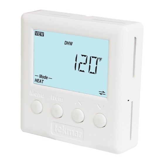
- Page 2 D 161 Data Brochure tekmarNet ® 4 Setpoint Control 161 08/07 Introduction Information Brochure The Setpoint Control 161 is a single stage heat setpoint control that can operate on an On / Off differential or can Choose controls to match operate on Pulse Width Modulation.
-
Page 3: Table Of Contents
Table of Contents Table of Contents ......2 Sequence of Operation ....19 Display and DIP Switches ....2 Mode 1 - On / Off Setpoint ...19 Dip Switches ......... 2 Mode 2 - Hot Tub ......19 Access Levels ....... 3 Mode 3 - DHW Tank .... -
Page 4: Access Levels
Access Levels The Access Level restricts the number of Menus, Items and Adjustments that can be accessed by the user. The Access Level setting is found in the Miscellaneous (MISC) menu. Select the appropriate access level for the people who work with the setpoint control on a regular basis. -
Page 5: Symbol Description
Symbol Description LOCK MODE OF OPERATION The Access Levels are Displays whether the device locked or a menu option is is in heating or off mode. visible but not adjustable. RELAY 1 OCCUPIED Displays when operating at Displays when relay contact the occupied temperature. -
Page 6: Application Overview
Default Item To set the default item in the VIEW Menu, display item for more than five seconds. After navigating menus, the display reverts back to the default item after 60 seconds of button inactivity. Continue to next Item Continue to next Item Continue to next Menu Application Overview... -
Page 7: Pulse Width Modulation
Mode 3 DHW Tank Heating Operation When heating, the setpoint control turns on Relay 1 when the temperature falls to 1/2 of the differential below the setpoint and turns off Relay 1 once the temperature reaches 1/2 of the differential above the setpoint. -
Page 8: Display Menus
7 of 32 © 2007 D 161 - 08/07... - Page 9 © 2007 D 161 - 08/07 8 of 36...
- Page 10 9 of 32 © 2007 D 161 - 08/07...
-
Page 11: Adjust Menu
© 2007 D 161 - 08/07 10 of 36... - Page 12 11 of 32 © 2007 D 161 - 08/07...
- Page 13 © 2007 D 161 - 08/07 12 of 36...
- Page 14 13 of 32 © 2007 D 161 - 08/07...
- Page 15 © 2007 D 161 - 08/07 14 of 36...
-
Page 16: Scene Menu
15 of 32 © 2007 D 161 - 08/07... -
Page 17: Schedule Menu
© 2007 D 161 - 08/07 16 of 36... -
Page 18: Miscellaneous Menu
17 of 32 © 2007 D 161 - 08/07... - Page 19 © 2007 D 161 - 08/07 18 of 36...
-
Page 20: Sequence Of Operation
Sequence of Operation Application Mode 1 - On / Off Setpoint SECTION A Application Mode 1 is a generic setpoint control operation using an on/off differential for heating. The sensor is required to be located at the temperature control point. The setpoint control can have an occupied temperature setting. -
Page 21: Mode 3 - Dhw Tank
Mode of Operation The hot tub mode of operation can be set to either Heat or Off. While set to Off, Relay 1 remains off. The Off setting should only be used when the hot tub is drained or when there is no possibility of freezing. Power should never be removed from the setpoint control as this will result in an error message on the tN4 system. -
Page 22: Mode 4 - Floor
Application Mode 4 - Floor SECTION D Application Mode 4 configures the setpoint control for floor warming and floor heating applications using pulse width modulation. Floor warming is not necessarily designed to heat the room, but to make the floor feel warm to the touch. This is common especially in bathrooms. -
Page 23: Remote Enable / Disable
Remote Enable / Disable SECTION E To use the Remote Enable / Disable feature, the setpoint control must be set to Mode 1 (Setpoint), 2 (Hot Tub), or 4 (Floor). When the setpoint control is connected to a tN4 system, a User Switch or tN4 Gateway can remotely signal a setpoint control (or multiple setpoint controls) to override the unoccupied temperature to temporarily operate at the occupied temperature. -
Page 24: Sensor Input
SECTION F The Setpoint Control 161 requires a temperature sensor (Universal Sensor 071 included) to be connected to the sensor input on the back of the control. All tekmar sensors are compatible. Choose the sensor type that best meets the requirements of the application. -
Page 25: Scenes
Scenes SECTION H Scenes are a system override feature available when the setpoint control is part of a tN4 system. Scenes allow the user to change the entire tN4 system to operate at preset temperatures. To use the scene function, go to the Scene menu and set the Scene setting to On. The tN4 scene can be changed through the scene menu on a tN4 thermostat, a tN4 User Switch or through a tN4 Gateway. -
Page 26: Restore Factory Defaults
Restore Factory Defaults SECTION I To restore the factory defaults, locate the Default item in the Miscellaneous menu and press and hold the Up and Down buttons for 1 second. The display will show “SELECT” and when completed it will show “DONE”. Temperature Units SECTION J The setpoint control can display temperatures in either Fahrenheit (°F) or in... - Page 27 Relay 1 System Pump In order to accommodate many different piping and pumping configurations, the setpoint control is able to choose whether a “system” pump is required to operate at the same time as Relay 1. This allows each manifold on a water temperature to have a “system”...
- Page 28 When the setpoint control is connected to a tN4 boiler bus, the address range is b:01 through to b:24. When the setpoint control is connected to the tN4 mix 1 bus, the address range is 1:01 through to 1:24. When the setpoint control is connected to the tN4 mix 2 bus, the address range is 2:01 through to 2:24.
-
Page 29: Error Messages
Error Messages Local Errors and Device Errors Error messages are used to indicate a problem somewhere in the system. There are two types of error messages: Local Errors and Device Errors. A Local Error indicates an error specific to a device. For example, a thermostat with a sensor short circuit will show a Sensor Short Error on its display. - Page 30 If the error message is a Device Error (if “DEV” or “DEV ERR” is shown on screen), read the address shown and go to the device with that address. That device will have a Local Error indicating specifically what the problem is. When the problem is corrected, the error message will automatically clear.
- Page 31 © 2007 D 161 - 08/07 30 of 36...
- Page 32 31 of 32 © 2007 D 161 - 08/07...
- Page 33 © 2007 D 161 - 08/07 32 of 36...
- Page 34 33 of 32 © 2007 D 161 - 08/07...
-
Page 35: Cleaning The Control
Cleaning the Control The control’s exterior can be cleaned using a damp cloth. Moisten the cloth with water and wring out prior to wiping the control. Do not use solvents or cleaning solutions. © 2007 D 161 - 08/07 34 of 36... - Page 36 Notes 35 of 32 © 2007 D 161 - 08/07...
-
Page 37: Warranty
The liability of tekmar under the Limited Warranty shall be limited to, at tekmar’s sole discretion: the cost of parts and labor provided by tekmar to repair defects in materials and / or workmanship of the defective product; or to the exchange of the defective product for a warranty replacement product; or...
Need help?
Do you have a question about the tekmarNet 4 Setpoint Control 161 and is the answer not in the manual?
Questions and answers