Advertisement
Quick Links
- Wiring Brochure
Universal Reset Module 423
1
2
Information
Application
Brochure
Brochure
Choose controls
Design your
to match
mechanical
application
applications
Overview
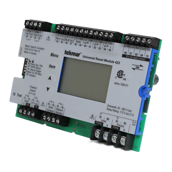
The following wiring brochure describes how to wire the tekmar Universal Reset Module 423. The 423 is to be installed in
an enclosure together with a tekmar Zone Manager. The 423 controls two boilers (on-off or modulating), DHW, and setpoint.
The wiring of tekmarNet
®
4 (tN4) components is simple and cost effective.
Stage1/
Stage 2/
Boil Enbl Setp Enbl
Mod1 (dc)
50 51
52
53
54
Meets Class B: Canadian
ICES & FCC Part 15
Menu
Made in Canada
/
Item
Boil Sens Sup / Ret
Off / DHW Sensor
Off / tekmar Stager
Boilers On-Off / Mod
Off / Rotation
Powered
Outputs
24 V (ac)
8 VA
1 VA
Test
71
72
73 74
DHW
24 V (ac)
C
Vlv
C
R
3
Rough-in
Wiring
Rough-in
wiring
instructions
+
–
+
–
C1
tN4
C
tN4
C2 tN4
Mod2 (dc)
Boiler
1
55
56
57
58
59 60
61
62
Universal Reset Module 423
75 76 77 78
DHW
Setpoint
Demand Demand
4
Wiring
Brochure
Wiring and
installation of
specific control
C3
tN4
DHW Com
Boil Com
2
3
63
64
65
66
67
68
69
Do not apply power
tN4
tektra 1006-01
Demands: 20 - 260 V (ac)
Relay Rating: 115 V (ac) 5 A
79
80
81
82
DHW
Primary
Pump
N
Pump
N
1 of 12
5
Data
Brochure
Control settings
and sequence of
operation
Out
70
tekmar wiring Enclosure (not included)
10 A
max
tekmar Zone Manager
© 2009
W 423
03/09
6
Job
Record
Record settings &
wiring details for
future reference
W 423 - 03/09
Advertisement

Related Manuals for Tekmar 423


Summary of Contents for Tekmar 423
- Page 1 Overview The following wiring brochure describes how to wire the tekmar Universal Reset Module 423. The 423 is to be installed in an enclosure together with a tekmar Zone Manager. The 423 controls two boilers (on-off or modulating), DHW, and setpoint.
- Page 2 Other controls that are injury or death. intended and certified as safety limits must be placed into © 2009 W 423 - 03/09 2 of 12...
- Page 3 4 (tN4) wiring enclosure. The enclosure comes with ® a Zone Manager pre-installed in the right side. Review the figure below to understand the installation of the 423. To Install the 423 1. Remove the front cover of the wiring enclosure by removing the two screws.
- Page 4 Mod1 (dc) Mod2 (dc) Boiler 50 51 59 60 Do not apply power Meets Class B: Canadian Universal Reset Module 423 ICES & FCC Part 15 Menu Made in Canada Boil Sens Sup / Ret Item Off / DHW Sensor...
- Page 5 Mod1 (dc) Mod2 (dc) Boiler 50 51 59 60 Do not apply power Meets Class B: Canadian Universal Reset Module 423 ICES & FCC Part 15 Menu Made in Canada Boil Sens Sup / Ret Item Connections Off / DHW Sensor...
- Page 6 Mod1 (dc) Mod2 (dc) Boiler 50 51 59 60 Do not apply power Meets Class B: Canadian Universal Reset Module 423 ICES & FCC Part 15 Menu Made in Canada Item Connections Boil Sens Sup / Ret Off / DHW Sensor...
- Page 7 Mod1 (dc) Mod2 (dc) Boiler 50 51 59 60 Do not apply power Meets Class B: Canadian Universal Reset Module 423 ICES & FCC Part 15 Menu Made in Canada Boil Sens Sup / Ret Item Off / DHW Sensor...
- Page 8 The following section explains how to wire individual them into the grooves provided as to isolate the low and devices to the Universal Reset Module 423. For step by high voltage wiring. step wiring refer to the terminal number on the right of •...
- Page 9 DHW and Boiler Sensor (tekmar 082) Terminals 66 - 69 Connect the two wires from the DHW Sensor 082 to the DHW and Com (66-67) terminals. The DHW Sensor is used Sensor mounted by the control to measure the DHW water temperature.
- Page 10 (dc) voltage between the Mod (dc) + and the control. the Mod (dc) - terminals (54-55, 56-57). The reading should vary between 0 V (dc) and 10 V (dc). © 2009 W 423 - 03/09 10 of 12...
- Page 11 DHW Demand terminals (75-76) or the • • When the demand device is off, less than 5 V (ac) should Setpoint Demand terminals (77-78). be measured between the terminals. 11 of 12 © 2009 W 423 - 03/09...
- Page 12 Web Site: www.tekmarcontrols.com Product design, software and literature are Copyright © 2009 by: All specifications are subject to change without notice. 12 of 12 tekmar Control Systems Ltd. and tekmar Control Systems, Inc. Printed in Canada. W 423 - 03/09.
Need help?
Do you have a question about the 423 and is the answer not in the manual?
Questions and answers