Table of Contents
Advertisement
Installation & Operation Manual
WiFi Snow Melting Control 671
Introduction
The WiFi Snow Melting Control 671 is designed to operate mechanical equipment to melt snow off an outdoor slab. It can
be used in hydronic or electric snow melting applications. This product uses a tekmar snow/ice detection sensor in order
to automatically melt snow using Pulse Width Modulation (PWM) and slab Outdoor Reset to maintain slab temperature.
It is capable of controlling a single boiler, a system pump, and providing a signal when melting is enabled.
Features
• Automatic software updates
• Automatic snow/ice detection
• Supports both inslab & retrofit aerial sensors
• Supports multiple zones with priority
• Manual Storm
• Idling
© 2019 tekmar 671 _ D - 08/19
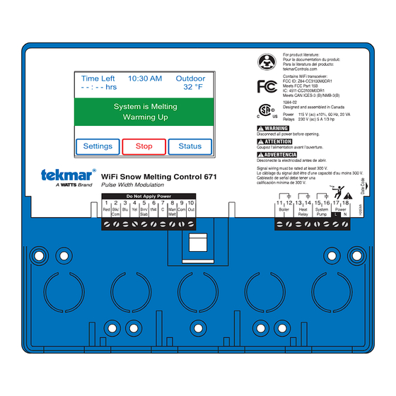
Time Left
10:30 AM
- - : - - hrs
Manual Melt
System is Melting
This is a hole
Warming Up
Settings
Stop
WiFi Snow Melting Control 671
Pulse Width Modulation
Do Not Apply Power
1
2
3
4
5
6
7
8
Red
Blk/
Blu
Yel
Brn/
tN4
C
Man
Com
Slab
Melt
• Warm Weather Shut Down
• Cold Weather Cut Off
• EconoMelt
• Tandem Snow/Ice Detection
• Pump exercising
Outdoor
32 °F
WARNING
Disconnect all power before opening.
ATTENTION
Status
Coupez l'alimentation avant l'ouverture.
ADVERTENCIA
Desconecte la electricidad antes de abrir.
Signal wiring must be rated at least 300 V.
Le câblage du signal doit être d'une capacité d'au moins 300 V.
Cableado de señal debe tener una
calificación mínima de 300 V.
9
10
Com
Out
Snow Melting Replaces: New
For product literature:
Pour la documentation du produit:
Para la literatura del producto:
tekmarControls.com
Contains WiFi transceiver:
FCC ID: Z64-CC3100M0DR1
Meets FCC Part 15B
IC: 4511-CC3100M0DR1
Meets CAN ICES-3 (B)/NMB-3(B)
1084-02
Designed and assembled in Canada
Power
115 V (ac) ±10%, 60 Hz, 20 VA
Relays
230 V (ac) 5 A 1/3 hp
11 12 13
14
15
16
17
18
Boiler
Heat
System
Power
Relay
Pump
L
N
671 _ D
08/19
Advertisement
Table of Contents

Related Manuals for Tekmar 671


Summary of Contents for Tekmar 671
- Page 1 WiFi Snow Melting Control 671 Cableado de señal debe tener una calificación mínima de 300 V. Pulse Width Modulation Do Not Apply Power 11 12 13 Blk/ Brn/ Boiler Heat System Power Slab Melt Relay Pump © 2019 tekmar 671 _ D - 08/19...
-
Page 2: Table Of Contents
Time Menu ..............20 Energy Menu ..............21 Monitor Menu ..............21 Setup – System Setup Menu ........22 Setup – Boiler Setup Menu .......... 22 tekmarNet Menu ............23 Toolbox Menu ............... 24 Override Menu .............. 24 Sequence of Operation ............25 Snow Melting Overview ..........25 Getting Started Congratulations on the purchase of your new Snow Melting Control! This manual covers the complete installation, programming and sequence of operation for this control. You will also find instruction on testing, commissioning, and troubleshooting the control and system that it operates. © 2019 tekmar 671 _ D - 08/19 2 of 36... -
Page 3: Important Safety Information
Read manual and all product labels BEFORE using the equipment. Do not use unless you know the safe and proper operation of this equipment. Keep this manual available for easy access by all users. Replacement manuals are available at tekmarControls.com • It is the installer’s responsibility to ensure that this control is safely installed according to all applicable codes and standards. • Improper installation and operation of this control could result in damage to the equipment and possibly even personal injury or death. • This control is not intended for use as a primary limit control. Other controls that are intended and certified as safety limits must be placed into the control circuit. Do not attempt to service the control. There are no user serviceable parts inside the control. Attempting to service the control voids the warranty. Radio Frequency Interference The installer must ensure that this control and its wiring are the interference by re-orientating or relocating the receiving isolated and/or shielded from strong sources of electromagnetic antenna, relocating the receiver with respect to this control, noise. Conversely, this Class B digital apparatus complies and/or connecting the control to a different circuit from that with Part 15 of the FCC Rules and meets all requirements of to which the receiver is connected. the Canadian Interference-Causing Equipment Regulations. Cet appareil numérique de la classe B respecte toutes les exi- However, if this control does cause harmful interference to gences du Règlement sur le matériel brouilleur du Canada. radio or television reception, which is determined by turning the control off and on, the user is encouraged to try to correct © 2019 tekmar 671 _ D - 08/19 3 of 36... -
Page 4: Installation
(x 5 back) (x 5 bottom) 3/16" (5 mm) (193 mm) Installation Location Choose the placement of the control early in the construction process to enable proper wiring during rough-in. • Keep the control dry. Avoid potential leakage onto the control. • Maintain relative humidity less than 90% in a non-condensing environment. • Avoid exposure to extreme temperatures beyond 32-122°F (0-50°C). • Install away from equipment, appliances, or other sources of electrical interference. • Install to allow easy access for wiring, viewing, and adjusting the display screen. • Install approximately 5 feet (1.5 m) off the finished floor. • Locate the control near pumps and/or zone valves if possible. • Provide a solid backing which the enclosure can be mounted to. Example: plywood or wall studs. • Use the conduit knockouts provided on the upper, lower, back and sides of the enclosure for wiring. © 2019 tekmar 671 _ D - 08/19 4 of 36... -
Page 5: Installing The Enclosure
The it onto the DIN rail. This will be a base also has holes that popular option for those who prefer line up with the mounting to mount the control inside a larger holes of most common electrical panel. The DIN Snap Kit electrical boxes. M9303 is sold separately. © 2019 tekmar 671 _ D - 08/19 5 of 36... -
Page 6: Rough-In Wiring
Line-Voltage Wiring - - - -------- ----------- --------- ----- --------------------- --------------------------- Pull two conductor 14 AWG cable, up to 500 feet (150 m) long, for the following equipment: • System pump • Boiler pump © 2019 tekmar 671 _ D - 08/19 6 of 36... -
Page 7: Sensor Wiring
Sensor ---- ------------------------- ---------------------- -------------------------- Wiring the Outdoor • Connect 18 AWG or similar wire to the two terminals provided Wires from in the enclosure and run the wires from the outdoor sensor outdoor sensor and sensor to the control. Do not run the wires parallel to telephone or common power cables. If the sensor wires are located in an area terminals on with strong sources of electromagnetic interference (EMI), tekmar control shielded cable or twisted pair should be used or the wires can be run in a grounded metal conduit. If using shielded cable, the shield wire should be connected to the Com ter- minal on the control and not to earth ground. • Follow the sensor testing instructions in this manual and connect the wires to the control. • Replace the front cover of the sensor enclosure. At the control: • Connect the outdoor sensor to terminals 9 and 10. © 2019 tekmar 671 _ D - 08/19 7 of 36... - Page 8 • Connect the black wire to terminal 2. • Connect the blue wire to terminal 3. • Connect the yellow wire to terminal 4. Snow Sensor Slab Sensor - - - - - - - - - ----- ----------- --------- ---------------- --------------------- --------------------- A Slab Sensor 072 or 073 can be installed either alone or together with a Snow Sensor 095. Blk/ Brn/ Slab If the Slab Sensor input is used: Connect the slab sensor to terminals 2 and 5. © 2019 tekmar 671 _ D - 08/19 8 of 36...
-
Page 9: Tekmarnet
The 671 can be connected to other tekmarNet communication compatible controls other tN4 using the tN4 bus. control If tekmarNet is used: • Connect tN4 on the 671 terminal 6 to the tN4 wiring terminal on the other device. • Connect C on the 671 terminal 7 to the C wiring terminal on the other device. • tekmarNet is polarity sensitive. Manual Melt Input The manual melt input allows the control to be manually switched to melting operation using a switch. This connection is optional. Melt If the Manual Melt input is used: Connect a switch to terminals 8 and 9. The switch may be either dry (no voltage) or a voltage signal up to 32 V (ac). © 2019 tekmar 671 _ D - 08/19 9 of 36... - Page 10 230 V (ac), 5 A, 1/3 hp terminals 15 and 16. For simplicity in wiring and troubleshooting, a separate System breaker for each pump is recommended. Pump • Connect the power source line wire (L) to terminal 16. • Connect a wire from terminal 15 to the pump L. • Connect a wire from the pump N back to the power source neutral. • Connect the ground wire (G) to the pump. Wiring the Input Power ---- ----------- --------- ----- - -------------------- ------------------------------- Provide a 15 A circuit for the input power. Power • Connect the 115 V (ac) line wire (L) to terminal 17. • Connect the neutral wire (N) to terminal 18. © 2019 tekmar 671 _ D - 08/19 10 of 36...
-
Page 11: Testing The Sensor Wiring
Step 5: Press Back button. Step 6: The following outputs can be operated: • System Pump relay • Heat Relay • Boiler Relay For each relay output • Use an electrical meter set to measure (ac) voltage. • Measure between the relay wiring terminals. • When the relay is off, the voltage should be 115 V (ac). • When the relay is on, the voltage should be 0 V (ac). Exiting the Hand Manual Override --------------- • Exit the Manual Override by selecting Auto. • Install the front cover. © 2019 tekmar 671 _ D - 08/19 11 of 36... -
Page 12: Manual Override - Maximum Heat
Step 1: Press Settings button. control remains off until manually changed back to Auto. This Step 2: Press Override button. allows the installer or end user to permanently disable the snow Step 3: Press Manual Override. melting system without removing power from the control. Step 4: Select Manual Override to Off. Step 5: Press Back button. The control is now in the off manual override. Step 6: Exit the Manual Override by selecting Auto. Access Levels The control is shipped pre-programmed with common settings. To change to the “Installer” access level: The control has an “Installer” access level that allows full • Step 1: Press the Settings button. access to all settings and a “User” access level that restricts • Step 2: Press the Toolbox button. the number of settings available. The control defaults to the • Step 3: Press Access Level. “User” access level after 12 hours of operation. • Step 4: Press the Installer radio button. © 2019 tekmar 671 _ D - 08/19 12 of 36... -
Page 13: User Interface
SYSTEM IS OFF • The snow melting system is off and is ready to detect snow or ice. • "Warm Weather Shut Down" is shown when the slab and outdoor temperature are above the WWSD setting. During WWSD, the snow will melt naturally due to warm outdoor temperatures. • "Cold Weather Cut Off" is shown when the outdoor temperature is below the CWCO setpoint. The outdoor temperature is so cold the heating system does not have capacity to melt snow. • "Melt Pending" is shown when the system is off during CWCO but will resume melting once the outdoor temperature increases above the CWCO setpoint. SYSTEM IS IDLING • The control is pre-heating the slab to the idling setpoint. This reduces the amount of time needed to reach the melting setpoint in the event snow or ice is detected. SYSTEM IN OVERRIDE / SYSTEM IN EXERCISING • The control is in a manual override for testing, commissioning or exercising. • The description field explains which type of override is active. © 2019 tekmar 671 _ D - 08/19 13 of 36... -
Page 14: Symbols
Symbols WARNING SYMBOL The control has a error message. Press the warning symbol to determine the error code and information on how to take corrective action. Refer to the Troubleshooting section for a list of error codes. Help Screen The display includes a Help screen for each setting. The Help screen provides a description of the setting that is identical to the description found in the Installation and Operation Manual. Status Menu Navigation Step 1: Press the Status button on the Home Screen. Step 2: Press either the System, Slab or Weather button. Step 3: Press up or down buttons to scroll through the list. © 2019 tekmar 671 _ D - 08/19 14 of 36... -
Page 15: System Status Menu
OUTDOOR – – –, User Current outdoor air temperature as measured by the outdoor sensor or from the tekmarNet -67 to 149°F system. “– – –” is displayed when no outdoor temperature reading is available. Installer (-55.0 to 65.0°C) SLAB TARGET – – –, User The slab target calculated by the control based on outdoor temperature and the melting, 32 to 110°F idling, or storm setpoints. “- - -” is displayed when no heat is required. Installer (0 to 43.0°C) SLAB SENSOR User -58 to 167°F Current slab sensor temperature. (-50.0 to 75.0°C) Installer SENSOR WATER STATUS User Current status of snow/ice sensor moisture detector. DRY or WET Installer © 2019 tekmar 671 _ D - 08/19 15 of 36... -
Page 16: Weather Status Screen
Weather Status Screen When WiFi is turned on, the control receives weather data from the Internet. The current weather, outdoor temperature and forecast snow fall information is displayed. Current outdoor conditions Settings Menu Navigation Step 1: Press the Settings button on the Home Screen. Step 2: Press one of the ten buttons. Step 3: Press up or down buttons to scroll through the list. Step 4: Press the highlighted setting name to change the setting value. © 2019 tekmar 671 _ D - 08/19 16 of 36... - Page 17 © 2019 tekmar 671 _ D - 08/19 17 of 36...
-
Page 18: Temp Menu
STORM RUN TIME hours Select the amount of storm run time to pre-heat the slab when advised of a winter storm Installer warning. Default = 8:00 hours Auto, Min, -2, -1, SENSITIVITY Select how sensitive Snow/Ice Sensor is to water detection. Mid, +1, +2, Max Installer Default = Auto WWSD Auto, 32 to 95°F S elect the temperature above which the snow melting system is shut off during warm Installer (0.0 to 35.0°C) weather. This allows the snow or ice to melt off the slab naturally. Default = Auto CWCO Off, -30 to 50°F Select the temperature below which the snow melting system is shut off during extremely (-34.5 to 10.0°C) Installer cold weather. Below this temperature, the heat loss of the slab exceeds the capacity of the Default = 10°F boiler or heating appliance. (-12.0°C) © 2019 tekmar 671 _ D - 08/19 18 of 36... -
Page 19: Away Menu
The home/away changes devices system-wide. All thermostats and controls that are grouped together as a location on the tekmar. All thermostats and controls on a tekmarNet system will also change together. Display Menu Description Range Access TEMPERATURE UNITS User Select Fahrenheit or Celsius temperature units. °F or°C Installer Conditions: Always available. SCREEN BRIGHTNESS User 0 to 100% Select the screen brightness. Installer Default = 75% Conditions: Always available. CLEAN SCREEN User The Clean Screen timer locks the screen for 10 seconds allowing the user to wipe the screen No,Yes with a moist cloth. Do not use solvents to clean the screen. Installer Conditions: Always available. © 2019 tekmar 671 _ D - 08/19 19 of 36... -
Page 20: Wifi Menu
• Then adjust with arrow buttons. 12 hr, TIME FORMAT User Select either 12 or 24 hour format. 24 hr Installer Conditions: Always available. Default = 12 hr Hawaii, Alaska, Pacific, Mountain, TIME ZONE User Central, Eastern, Select the location's time zone. Atlantic, Installer Conditions: Available when Time Source is set to Manual. NFLD, (Newfoundland) DAYLIGHT SAVINGS User Off or On Set Daylight Savings to On to automatically adjust for time changes in the spring and fall. Default = On Installer Conditions: Always available. © 2019 tekmar 671 _ D - 08/19 20 of 36... -
Page 21: Energy Menu
Records the highest measured slab temperature since the counter was last reset. (-50.0 to 75.0°C) Conditions: Available when Snow/Ice is set to In-slab or Slab Sensor is set to On SLAB SENSOR LOW -58 to 167°F Installer Records the lowest measured slab temperature since the counter was last reset. (-50.0 to 75.0°C) Conditions: Available when Snow/Ice is set to In-slab or Slab Sensor is set to On OUTDOOR HIGH -67 to 149°F Installer Records the highest measured outdoor air temperature since the counter was last reset. (-55.0 to 65.0°C) Conditions: Always available. OUTDOOR LOW -67 to 149°F Installer Records the lowest measured outdoor air temperature since the counter was last reset. (-55.0 to 65.0°C) Conditions: Always available. RESET ALL? Installer Resets all the counters in the monitor menu at once. No, Yes Conditions: Always Available. © 2019 tekmar 671 _ D - 08/19 21 of 36... -
Page 22: Setup - System Setup Menu
Installer Sensor 090 or 094, or a Snow Sensor 095. Default = 3 days Conditions: Always available. Control, OUTDOOR SENSOR tekmarNet, Select if the outdoor air temperature is measured by the control, by a tekmarNet system or Installer by the Internet weather service. Internet Conditions: Always available. Default = Control Setup – Boiler Setup Menu Description Range Access BOILER TYPE Enable, Select the type of boiler operated by the control. Installer Enable = Boiler relay turns on the heat source. Control Control = Call for heat to tekmarNet control. Conditions: Available when the 671 is connected to a tekmarNet system. © 2019 tekmar 671 _ D - 08/19 22 of 36... -
Page 23: Tekmarnet Menu
A User Switch or Gateway may be used to manually start melting the zone. Set the Melt Installer 1 to 12 Group number to the corresponding Setpoint Enable number on the User Switch. STORM GROUP Installer 1 to 12 A User Switch may be used to manually start storm operation of the snow zone. Set the Melt Group number to the corresponding Setpoint Enable number on the User Switch. Off, Conditional, PRIORITY Select the priority of the snow melting system. Full Installer Default = Off AWAY SCENE Off or On Installer Select if the control should accept or ignore the away command from a tekmarNet system. Default = On Conditions: Always available. TN4 SYSTEM PUMP Select if the system pump located on the tekmarNet System Control should operate when Installer Off or On the snow melt zone is heating. © 2019 tekmar 671 _ D - 08/19 23 of 36... -
Page 24: Toolbox Menu
Off or On BOILER ENABLE Installer Manually turn on the boiler during the HAND Manual Override. Default = Off 0:10 to 72:00 User HAND DURATION hours Select the amount of time that the HAND Override is in effect before returning to Automatic operation. Installer Default = 0:10 hour 0:10 to 72:00 User MAX HEAT DURATION hours Select the amount of time that Max Heat is in effect before returning to Automatic operation. Installer Default = 24:00 hour 0:10 to 72:00 User PURGE DURATION hours Select the amount of time that the Purge is in effect before returning to Automatic operation. Installer Default = 0:10 hour © 2019 tekmar 671 _ D - 08/19 24 of 36... -
Page 25: Sequence Of Operation
090 or 094 Detects Water 090 or 094 and Slab Dry and Idle Melting Add Melt Time Elapses Auto Push STOP Button Start/ WWSD Auto Stop Snow/Ice Sensor 090 or 094 Gateway 482 or 486 Stop Message Enters Exits CWCO Melt CWCO Suspended The slab temperature must reach the slab target in order for the must be set to provide the full capacity of the heating appliance. system to shut off automatically. The capacity of the heat source For example, boiler aquastats should be set to 180°F (82°C). must be sized to ensure melting as low as the cold weather cut Failure to meet these requirements may result in the snow melting off. In addition, the heat source maximum temperature setting system not automatically shutting off when the slab is dry. © 2019 tekmar 671 _ D - 08/19 25 of 36... -
Page 26: Melt - Economelt
When moisture is detected and the control is not in WWSD efficiency. The control continually monitors the snow sensor or CWCO or Away, the control automatically starts the snow for the presence of moisture and slab temperature conditions melting system. The snow melting system operates to heat in which snow or ice may be present. When moisture is the slab to the slab target temperature and continues to detected, the control will show “Sensor Water Status Wet” operate until the time set by the Manual Melt Run Time in the in the Slab Status menu. When the sensor is dry the control Temperatures menu elapses. If the 095 re-detects water, the will show “Sensor Water Status Dry”. The control includes a timer is restarted to operate for the full run time. Sensitivity setting in the Temperatures menu that allows the installer to adjust the amount of moisture required to start and 095 Redetects Water 095 Detects Water Melting Idle Manual Melt Run Time Elapses Push Stop Button Auto Start/ Timed Gateway 482 or 486 Stop Message Stop Snow Sensor 095 WWSD CWCO © 2019 tekmar 671 _ D - 08/19 26 of 36... -
Page 27: Tandem Snow/Ice Detection
Sensor Sensor Sensor Run Time has fully elapsed, it sends a signal to the tracked zones that zone 1 has stopped. Each zone can continue to operate to complete their own Additional Melt Time after which the zone stops heating and returns to the Off or Idle operation. Zones with priority selected start after zone 1 has finished Records Repeats Repeats melting and repeat the same run time as zone 1. Run Time Zone 1 Run Zone 1 Run Time + Add Time + Add Melt Time Melt Time © 2019 tekmar 671 _ D - 08/19 27 of 36... -
Page 28: Idle Operation
Storm - - - - - - - - - --------- ---------- ------- Gateway 482 Storm Enable The storm operation is manually started by a User Switch 480 and 481 or a Gateway 482. The manual storm uses the Storm Group number in the tekmarNet menu. Storm Storm Run Time Elapses Setup Procedure User Switch Button Step 1: Set the 671 Storm Group number from 1 to 12. The Gateway 482 Storm Disable default is 12. Away scene Step 2: Set the User Switch or the Gateway to use the corre- WWSD sponding Storm Group number. CWCO When the User Switch button is pressed, the 671 will enter the Storm Operation. Likewise, activating the Storm Group on the Gateway cause the 671 to enter the Storm Operation. forecast Then © 2019 tekmar 671 _ D - 08/19 28 of 36... -
Page 29: Slab Temperature Control
Priority does not apply when the application mode is set to snow melting system. The trade off is that some snow melt Boiler. In this mode, the boiler is dedicated to a single snow zones may not be able to melt as soon as the snow fall begins melting zone so priority is no longer applicable. and the user must tolerate snow accumulation on the slab. The snow melt system using Snow Melting Control 654, tekmarNet 670 and 671 may have up to 12 snow melt zones. Zone 1 has the highest priority and zone 12 has the lowest. The priority setting in the tekmarNet menu allows the installer ® to select the level of zone priority for the entire snow melt system. Changing the priority setting on one control will update on all other snow melt controls at the same time. The zone priority has 3 setting levels. There is some risk that lower priority zones may ice up when they are shut off by the higher priority zone. For example, if a high priority zone should finish melting and allow a lower priority zone Snow Melt Snow Melt to start melting, and then a new snow fall occurs, the high Zone 1 Zone 2 priority zone will shut off the lower priority zones. This may potentially allow the lower priority zones to ice over. The © 2019 tekmar 671 _ D - 08/19 29 of 36... - Page 30 Zone 2 Priority = Conditional MELT The zone with the lower priority starts melting when the zone with higher priority is warm enough to melt snow or ice. Zone 1 This setting is recommended when the boiler plant capacity is sized to be larger than the heat loss of each zone with some extra capacity. MELT Zone 2 Priority = Full MELT The zone with the lower priority starts melting once the zone with higher priority has finished melting all snow or Zone 1 ice from the slab. This setting is recommended when the boiler plant capacity is sized to be the same as the heat loss of each zone at design conditions. MELT Zone 2 © 2019 tekmar 671 _ D - 08/19 30 of 36...
-
Page 31: Warm Weather Shut Down
Time Clock The control has a built-in time clock that can be set manually. month and year are entered. Use the Time menu to set the A battery-less backup allows the control to keep time for up correct time, day, month and year. to 4 hours without power. The time clock supports automatic adjustment for Daylight Saving Time (DST) once the day, Away Operation While on vacation and away from a building, it may not be • Away menu necessary to operate the snow melting system. The away • tekmarNet User Switch 480 or 481 feature allows the user to shut off the snow melting system to • tekmarNet Gateway 482 or 486 maximize energy savings. The Away feature can be activated through the: tekmarNet Scene Operation The tekmarNet system supports up to 8 scenes. The 671 supports tekmarNet scenes 1 (normal operation) and 2 (away). During tekmarNet scenes 3 through 8, the 671 remains in scene 1 (normal operation). © 2019 tekmar 671 _ D - 08/19 31 of 36... -
Page 32: Pulse Width Modulation Zone Operation
Pulse Width Modulation Zone Operation Relay operation: The control operates the system pump to operate continuously during melt, idle and storm operation. The boiler relays and heat • System pump — operates continuously during melting, pumps relays operate on a 20-minute pulse width modulation idling or storm cycle. The relay on time is determined by the calculated slab • Heat relay — cycles on/off using Pulse Width Modulation to target and by the measured slab temperature reading. As control the slab temperature the slab temperature reaches the slab target, the on time per • Boiler — cycles on/off using Pulse Width Modulation to con- cycle of the relay is reduced to prevent the slab temperature trol the slab temperature from overshooting. If no slab sensor is installed the heat relay remains on 100% of the time until the Melt circle has completed. When connected to a tekmarNet system, the 671 can operate a boiler (Boiler Type set to Enable) or it can call for heat from the tekmarNet boiler control (Boiler Type set to Control) © 2019 tekmar 671 _ D - 08/19 32 of 36... -
Page 33: Outdoor Sensor
BOILER SETUP MENU MEMORY ERROR A memory error occurred and the control reloaded the factory default settings. The control stops operation until all settings in the Boiler Setup menu are checked. To clear the error, set the access level to Installer and check all settings in the Boiler Setup menu. tekmarNet MENU MEMORY ERROR A memory error occurred and the control reloaded the factory default settings. The control continues operation as normal. To clear the error, set the access level to Installer and check all settings in the tekmarNet menu. WiFi MENU MEMORY ERROR A memory error occurred and the control reloaded the factory default settings. The control continues operation as normal. To clear the error, set the access level to Installer and check all settings in the WiFi menu. MAX MELT DAYS ERROR The control has operated in melting for the time set by the Maximum Melt Days setting. This error is usually created when there is a mechanical system failure resulting in the snow melt slab not heating correctly. Clear the error message by touching the Reset button while viewing the error message. tekmarNet Communications Error The tekmarNet communication bus has either an open or a short circuit. The result is that there are no communications. The error clears automatically once the wiring fault has been corrected. To force the error to clear while allowing a short or open circuit to continue, touch the Reset key. © 2019 tekmar 671 _ D - 08/19 33 of 36... -
Page 34: Error Messages (2 Of 2)
SNOW SENSOR BLUE WIRE OPEN CIRCUIT ERROR Due to an open circuit, the control is unable to read the blue wire connected to the Snow/Ice Sensor 090 or 094, or the Snow Sensor 095 on terminals 2 and 3. The control can no longer automatically detect snow or ice, but manual start of the snow melting system is still available. Check the snow/ice sensor or snow sensor blue and black wires and any wire splices for open circuits according to the sensor installation manual. It may be necessary to replace the sensor. Once the error has been corrected, the error message automatically clears. SNOW SENSOR BROWN WIRE SHORT CIRCUIT ERROR The control is unable to read the brown wire connected to the Snow/Ice Sensor 090 or 094. Check the snow/ice sensor brown and black wires for faults. It may be necessary to replace the sensor. Once the error has been corrected, the error message automatically clears. SNOW SENSOR BROWN WIRE OPEN CIRCUIT ERROR Due to an open circuit, the control is unable to read the brown wire connected to the Snow/Ice Sensor 090 or 094 on terminals 2 and 5. Idling and Storm is disabled and energy saving features such as Warm Weather Shut Down (WWSD) and Cold Weather Cut Off (CWCO) are operated using the outdoor temperature only. Check the snow/ice sensor brown and black wires for open circuits according to the sensor installation manual. It may be necessary to replace the sensor. Once the error has been corrected, the error message automatically clears. © 2019 tekmar 671 _ D - 08/19 34 of 36... -
Page 35: Frequently Asked Questions
Remaining Run System manually started. Time Slab and Slab The slab must reach the slab target temperature in order for the system to shut off. Target Lower the cold weather cut off (CWCO) or increase the boiler aquastat setting. Snow on slab System has been manually stopped and the automatic snow/ice sensor never dried, but system did System is Off thereby preventing the system from automatically starting. not start Cannot register Check WiFi signal May need to move control or router location. device strength © 2019 tekmar 671 _ D - 08/19 35 of 36... -
Page 36: Technical Data
The liability of tekmar under the Limited Warranty shall be limited to, at tekmar’s OF MERCHANTABILITY AND FITNESS FOR A PARTICULAR PURPOSE, DURA- sole discretion: the cost of parts and labor provided by tekmar to repair defects in BILITY OR DESCRIPTION OF THE PRODUCT, ITS NON-INFRINGEMENT OF materials and / or workmanship of the defective product;...
Need help?
Do you have a question about the 671 and is the answer not in the manual?
Questions and answers