Advertisement
Quick Links
- Wiring Brochure
Zone Expansion Module 325
1
2
Information
Application
Brochure
Brochure
Choose controls
Design your
to match
mechanical
application
applications
Overview
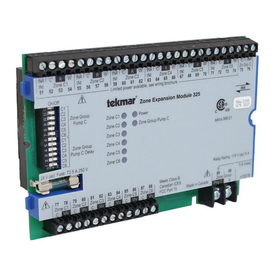
The following wiring brochure describes how to wire the tekmar Zone Expansion Module 325. The 325 is to be installed
in an enclosure together with a tekmar Zone Manager. The 325 controls up to six tekmarNet
24 V (ac) zone valves, and one 115 V (ac) Zone Group Pump. The wiring of tekmarNet
and cost effective.
tN4
C
R
W
tN4
C
R
W
tNt
Zone C1
tNt
Zone C2
51
52
53
54
55
56
57
58
On/Off
C1
C2
C3
Zone Group
C4
Pump C
Zone C1
C5
C6
Zone C2
C1
Zone C3
C2
C3
Zone Group
Zone C4
C4
Pump C Delay
C5
Zone C5
C6
Zone C6
24 V (ac) Fuse: T2.5 A 250 V
77
78
79
80
81
82
83
Zone C1
Zone C2
Zone C3
Zone C4
C
Vlv
C
Vlv
C
Vlv
3
Rough-in
Wiring
Rough-in
wiring
instructions
tN4
C
R
W
tN4
C
R
W
tN4
tNt
Zone C3
tNt
Zone C4
tNt
59
60
61
62
63
64
65
66
67
Limited power available, see wiring brochure
Zone Expansion Module 325
Power
Zone Group Pump C
Meets Class B:
84
85
86
87
88
Canadian ICES &
Zone C5
Zone C6
FCC Part 15
C
Vlv
C
Vlv
C
Vlv
4
Wiring
Brochure
Wiring and
installation of
specific control
C
R
W
tN4
C
R
W
C
tN4
Zone C5
tNt
Zone C6
Zn Grp C
68
69
70
71
72
73
74
75
76
tN4
tektra 998-01
Relay Rating: 115 V (ac) 5 A
5 A (max)
89
90
Zone Group
Made in Canada
H7001B
Pmp C
N
1 of 12
5
6
Data
Brochure
Control settings
Record settings &
and sequence of
wiring details for
operation
future reference
®
4 (tN4) thermostats, six
®
4 (tN4) components is simple
tekmar wiring Enclosure (not included)
tekmar Zone Manager
© 2008
W 325
12/08
Job
Record
W 325 - 12/08
Advertisement

Related Manuals for Tekmar 325


Summary of Contents for Tekmar 325
- Page 1 Overview The following wiring brochure describes how to wire the tekmar Zone Expansion Module 325. The 325 is to be installed in an enclosure together with a tekmar Zone Manager. The 325 controls up to six tekmarNet ®...
-
Page 2: Table Of Contents
Other controls that are injury or death. intended and certified as safety limits must be placed into © 2008 W 325 - 12/08 2 of 12... -
Page 3: Module Installation
® 4 (tN4) wiring enclosure. The enclosure comes with a Zone Manager pre-installed in the right side. Review the figure below to understand the installation of the 325: To Install the 325 1. Remove the front cover of the wiring enclosure by removing the two screws. - Page 4 Electrical Application 325 E1 Description: tekmarNet ® 4 Zone Expansion Module 325, six tekmarNet ® 4 Thermostats, six zone valves, zone group pump. External tN4 C Connection Thermostat Thermostat Thermostat Thermostat Thermostat Thermostat tN4 C R Rh1 W1 tN4 C R Rh1 W1...
- Page 5 Electrical Application 325 E2 Description: tekmarNet ® 4 Zone Expansion Module 325, six tekmarNet ® 4 Thermostats, six zone valves. External tN4 C Connection Thermostat Thermostat Thermostat Thermostat Thermostat Thermostat tN4 C R Rh1 W1 tN4 C R Rh1 W1...
-
Page 6: Wiring The Control
Module 325 Wiring the Zone Valve Outputs Terminals 77-88 Up to six 24 V (ac) zone valves may be wired to the 325. Zone Expansion The maximum load for each zone valve is determined by Module 325 the relay rating of the thermostat operating that zone. - Page 7 Wiring the Zone Group Pump Terminals 89-90 Zone Expansion The 325 operates one Zone Group Pump. Module 325 • • If a Zone Group Pump C is used, the pump is wired directly to terminals 89 and 90. • • The pump’s ground wire is connected to the ground Zone Group screw provided in the wiring chamber.
-
Page 8: Adding Extra Va
3. Mount and wire the external transformer according to the manufacturer’s instructions. Example: Zones C1, C2, C3 operate off internal 325 transformer. Zones C4, C5, C6 operate off external 24 V (ac) NEC / CEC Class 2 transformer. Thermostat Thermostat... -
Page 9: Troubleshooting The Control
4. Using an electrical test meter, check for continuity. 5. Reconnect the wires to the proper terminals. 2. Disconnect the two wires (tN4 and C) at one end and connect them together. 9 of 12 © 2008 W 325 - 12/08... - Page 10 0 V (ac) and the pump should be off. • • When the Zone Group Pump C light is on, the reading should be 115 V (ac) + / – 10% and the pump should be running. © 2008 W 325 - 12/08 10 of 12...
- Page 11 Notes 11 of 12 © 2008 W 325 - 12/08...
-
Page 12: Technical Data
Web Site: www.tekmarcontrols.com Product design, software and literature are Copyright © 2008 by: All specifications are subject to change without notice. 12 of 12 tekmar Control Systems Ltd. and tekmar Control Systems, Inc. Printed in Canada. W 325 - 12/08.
Need help?
Do you have a question about the 325 and is the answer not in the manual?
Questions and answers