Table of Contents
Advertisement
- Data Brochure
Universal Reset Module 422
1
2
Information
Application
Brochure
Brochure
Choose controls
Design your
to match
mechanical
application
applications
Introduction
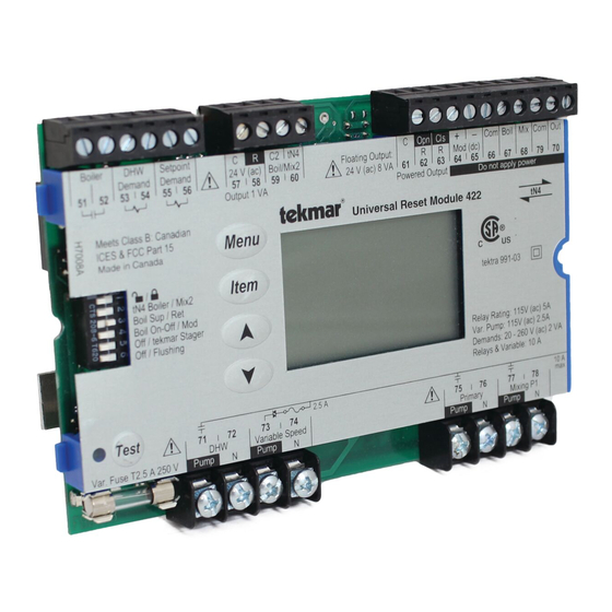
The Universal Reset Module 422 provides outdoor reset to a hydronic heating system in order to maximize comfort and
efficiency. The 422 can operate a single on / off boiler or a single modulating boiler. The 422 can override the outdoor reset
water temperature to provide Domestic Hot Water or Setpoint operations. The 422 can operate two outdoor reset water
temperatures, either one boiler water temperature and a single mix water temperature, or two mix water temperatures. To
operate two mixing devices, a Mixing Expansion Module must be connected to the 422. The single mix output can operate
a floating action mixing valve or a variable speed injection pump.
Features:
• tN4 Compatible
•
• • Two Outdoor Reset Temperatures
• • Single On-Off or Modulating Boiler
• • Powered Pump Outputs
Boiler
DHW
Demand
51 52
53 54 55
/
tN4 Boiler / Mix 2
Boil Sens Sup / Ret
Boiler On-Off / Mod
Off / tekmar Stager
Off / Flushing
Meets Class B: Canadian
ICES & FCC Part 15
Made in Canada
Test
Var. Pump Fuse
T2.5 A 250 V
3
Rough-in
Wiring
Rough-in
wiring
instructions
Setpoint
C
R
C2 tN4
Demand
24 V (ac) Boil/Mix2
56
57
58
59
60
Output 1 VA
Menu
Item
71
72
73
74
DHW
Variable Speed
Pump
N
Pump
N
4
Wiring
Brochure
Wiring and
installation of
specific control
• • DHW Operation
• • Variable Speed Injection Pump
• • Floating Action Valve
• • Includes Sensors
C
Opn Cls
Floating Output:
R
24 V (ac) 8 VA
61
62
Powered Output
Universal Reset Module 422
2.5 A
1 of 32
5
6
Data
Brochure
Control settings
Record settings &
and sequence of
wiring details for
operation
future reference
+
–
Com Boil Mix Com Out
R
Mod (dc)
63 64
65
66
67
68
69
Do not apply power
tN4
tektra 991-03
Var. Pump: 115 V (ac) 2.5 A
Demands: 20 - 260 V (ac)
Relay Rating: 115 V (ac) 5 A
75
76
77
78
Primary
Mix Sys P1
Pump
N
Pump
N
© 2007
D 422
08/07
Job
Record
70
10 A
max.
D 422 - 08/07
Advertisement
Table of Contents

Subscribe to Our Youtube Channel
Related Manuals for Tekmar Universal Reset Module 422


Summary of Contents for Tekmar Universal Reset Module 422
- Page 1 Introduction The Universal Reset Module 422 provides outdoor reset to a hydronic heating system in order to maximize comfort and efficiency. The 422 can operate a single on / off boiler or a single modulating boiler. The 422 can override the outdoor reset water temperature to provide Domestic Hot Water or Setpoint operations.
-
Page 2: Table Of Contents
Table of Contents Table of Contents ............2 Boiler Temperature Control ........19 Display and DIP Switches ..........2 tekmar Stager Operation ........21 Dip Switch Settings ..........2 Boil Enable ............22 Access Level ............3 Direct Fired - DHW Tank as a Heat Source ..22 Display and Symbols Description......4... -
Page 3: Access Level
Controls 264, 265, and 268. determines the boiler water temperature. Set the boiler’s • • If a tekmar Stager is installed, set to tekmar Stager. The aquastat at least 20°F (11.0°C) higher than the Boiler 422 will then provide the stager with a target temperature Maximum setting. -
Page 4: Display And Symbols Description
Display Symbols Description Item Field Menu Field Displays an Displays the abbreviated name current menu of the selected item Status Field Number Field Displays the current Displays the status of the control’s current value of inputs, outputs and the selected item operation. -
Page 5: User Interface
User Interface Adjusting a Setting Use the User Interface available on the Liquid Crystal Display (LCD) to setup and monitor the operation of the system. To adjust a setting: Use the four push buttons to the left of the LCD (Menu, Item, Up, Down) to select settings. -
Page 6: Display Menus
Display Menus View Menu (1 of 2) The View menu items display the current operating temperatures and status information of the system. Item Field Range Access Description OUTDOOR SECTION B -76 to 149°F Current outdoor air temperature as measured by the (-60.0 to 65.0°C) outdoor sensor. - Page 7 View Menu (2 of 2) Item Field Range Access Description BOILER TARGET SECTION C The boiler target is the temperature the control is currently trying to maintain at the boiler supply sensor. “– – –” is – – –, 35 to 230°F displayed when no heat is required for boiler zones.
-
Page 8: Adjust Menu
Adjust Menu (1 of 5) The Adjust Menu items are the programmable settings used to operate the mechanical equipment. Item Field Range Access Description OUTDOOR DESIGN SECTION B -60 to 45°F (-51.0 to 7.0°C) The design outdoor air temperature used in the heat Default = 10°F loss calculations for the heating system. - Page 9 Adjust Menu (2 of 5) Item Field Range Access Description MIX 1 MOTOR SECTION G The time that the Mix 1 actuating motor requires to 30 to 230 seconds operate from fully closed to fully open. Default = 105 Note: This item is only available when the Mix 1 Mode setting is set to floating action (FLt).
- Page 10 Note: This item is only available when the Boiler Sensor Sup / Ret DIP switch is set to Sup, the Boiler On-Off / Mod DIP switch is set to Mod and the tekmar stager DIP switch is set to OFF.
- Page 11 Note: This item is only available when the Boiler Default = 0% Sensor Sup / Ret DIP switch is set to Sup, the Boiler On-Off / Mod DIP switch is set to Mod, and the tekmar stager DIP switch is set to OFF. MAXIMUM MODULATION SECTION C The maximum percent modulation of the burner.
- Page 12 Adjust Menu (5 of 5) Item Field Range Access Description SETPOINT OCCUPIED SECTION J 60 to 220°F The minimum boiler target temperature when a (15.5 to 104.5°C) setpoint demand is present during the Wake and Occupied periods. Default = 180°F (82.0°C) Note: This item is only available when Setpoint Mode is set 1 through 4.
-
Page 13: Miscellaneous Menu
Misc (Miscellaneous) Menu (1 of 1) The Miscellaneous Menu Items set control and display options such as access level and temperature units. Item Field Range Access Description ACCESS LEVEL The access level of the control. The access column InS (Installer) shows which items are visible in each access level. -
Page 14: Testing The Control
Only trained, qualified and competent personnel should operate the Test button. IF the On-Off / Modulating DIP switch is set to Modulating or the tekmar Stager / Off DIP switch is set to tekmar Stager: Press and Hold... - Page 15 Max Heat Zone Test The control has a function called Max Heat. In this mode, In Zone Test mode, each tN4 device is individually turned the control turns on and operates the system up to the on one at a time. The control tests each zone for up to 5 maximum set temperatures as long as there is a demand minutes of no button activity.
-
Page 16: Sequence Of Operation
4 (tN4) communicates between tN4 devices (thermostats, Reset Module and Expansion Modules). The Universal Reset Module 422 is the system control Each tN4 device is connected to a tN4 communication for a hydronic heating system. The 422 operates a single bus using two wires. - Page 17 Terminal Unit Radiator (5) Terminal type 5 is a radiator terminal unit has a large heated There is a terminal unit setting for each tN4 bus. The surface that is exposed to the room. A radiator provides Terminal Unit setting is found in the Adjust menu. heat to the room through radiant heat transfer and natural convection.
- Page 18 Boiler Outdoor Reset Mix 1 and Mix 2 Outdoor Reset There is a water temperature and therefore a characterized Each tN4 communication bus operates on a separate water heating curve for each communication bus. When using temperature. Therefore a separate characterized heating boiler temperature water to heat zones, the installer will curve is required for Mix 1 and, if the tN4 DIP switch is be required to set a boiler characterized heating curve.
-
Page 19: Boiler Temperature Control
Boiler Temperature Control Section C The 422 is able to operate a single, hot water, on-off or Boiler Minimum modulating boiler as a heat source. For proper operation of The boiler minimum is the lowest temperature that the the boiler, the 422 must be the only control that determines control is allowed to use as a boiler target temperature. - Page 20 On-Off Boiler Operation Modulating Boiler Operation If the heat source is an On-Off Boiler, the Boil On-Off / Mod The 422 can operate a single hot-water modulating boiler. DIP switch must be set to On-Off. This requires the use of the Mod (dc) output on the 422. To operate a modulating boiler, the Boil On-Off / Mod DIP Differential switch must be set to Mod.
-
Page 21: Tekmar Stager Operation
422 allows for a connection to a tekmar Boiler switch settings are required: Control 264, 265, or 268. The 422 uses the modulating 1. Set the 422 Off / tekmar Stager DIP switch to tekmar output to provide a 0-10 V (dc) signal to the external input Stager. -
Page 22: Boil Enable
Stager (Boiler Control 264, 265, 268), operating use of a mixing device. This protects the boiler sustained multiple boilers or multiple stages, then the boiler sensor flue gas condensation and thermal shock. -
Page 23: Domestic Hot Water Temperature Operation
Variable Speed Injection Mix 1 and Mix 2 Minimum A standard wet rotor circulator can be connected to the The Mix 1 and Mix 2 Minimum settings are the lowest Variable Speed output on the control for Mix 1 and on temperature that the control is allowed to use as a mix a Mixing Module for Mix 2. - Page 24 DHW Mode and Priority Operation DHW MODE 3 - DHW in Primary / Secondary no Priority When a DHW Demand is present, the DHW Pump contact The control has four different settings available for DHW is closed and the primary pump (P1) is operated. Mode that affect pump operation.
-
Page 25: Dhw With Low Temperature Boilers
Conditional DHW Priority DHW Mixing Purge If the boiler supply temperature is maintained at or above the After DHW operation, the boiler is extremely hot. At the same required temperature during DHW generation, this indicates time, the heating zones may have cooled off considerably that the boiler has enough capacity for DHW and possibly after being off for a period of time. - Page 26 Boiler Target During Setpoint Setpoint Mode 3 – Setpoint in Primary / Secondary Whenever a setpoint demand is present, the primary pump The boiler target temperature during a Setpoint Demand is (P1) is turned on and the boiler is operated to maintain the increased to at least the Setpoint setting.
-
Page 27: Pump Operation
Pump Operation Section K Primary Pump Mix System Pump P1 The primary pump is switched on in the following The mixing pump P1 is switched on only when there is a situations: Mix 1 Demand and that zone’s thermostat has H1 Pump set to On. -
Page 28: Error Messages
Error Messages Local Errors and Device Errors Error messages are used to indicate a problem somewhere in the system. There are two types of error messages: Local Errors and Device Errors. A Local Error indicates an error specific to a device. For example, a thermostat with a sensor short circuit will show a Sensor Short Error on its display. - Page 29 Error Messages (1 of 3) Error Message Description ADJUST ERROR The control failed to read the Adjust menu settings, and reloaded the factory default settings. Operation stops until you check the Adjust menu settings. Note: To clear the error, the access level must be set to Advanced and the settings in the Adjust menu must be checked.
- Page 30 Error Messages (2 of 3) Error Message Description MIXING EXPANSION MODULE CONFLICT A Mixing Expansion Module is connected to the Boiler bus. The Mixing Expansion Module must be removed from the Boiler bus or the bus must be set to Mix 2 via the tN4 Boiler / Mix2 DIP switch.
-
Page 31: Troubleshooting
There is a DIP switch settings conflict. The tekmar Stager DIP switch is set to On and the Boiler Sensor DIP switch is set to Ret. Once the Boiler Sensor DIP switch is set to Sup or the tekmar Stager DIP switch is set to Off, the error message clears. -
Page 32: Warranty
Purchaser shall indem- such Product sale and acknowledges that it has read nify and hold tekmar harmless from and against any and all and understands same. claims, liabilities and damages of any kind or nature which...
Need help?
Do you have a question about the Universal Reset Module 422 and is the answer not in the manual?
Questions and answers