Table of Contents
Advertisement
Quick Links
- Data Brochure
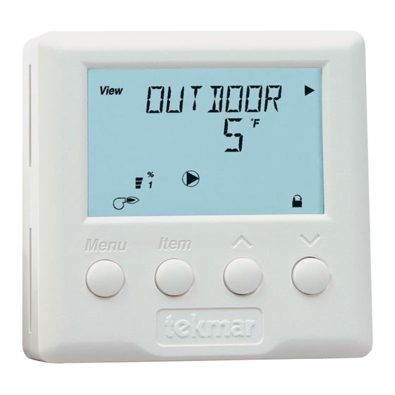
Remote Display Module (RDM) 040
View
° F
Occ
%
1 2
DHW
1
Menu
Item
Installation
STEP ONE
Place a screwdriver or similar object into the small slot located in the top
of the RDM. Push the screwdriver against the plastic tab, and pull the top
of the front cover so that it pivots around the bottom edge of the RDM.
STEP TWO
The base of the RDM should be securely installed in the desired location.
Mount the RDM directly to the desired location using two #6 - 1" screws.
The screws are inserted through the mounting holes and must be
securely fastened to the desired location. If possible, at least one of the
screws should enter a wall stud or similar surface. If the RDM is to be
mounted to a 2" x 4" electrical box, order an Adaptor Plate 007. This plate
mounts to the electrical box and the RDM will then mount to the plate.
STEP THREE
Run 18 AWG twisted pair or similar wire between the RDM and the control. Insert the wires through the hole provided in the back of
the RDM enclosure and connect them to the Com and the tekmar Net
power lines as this may interfere with the operation of the RDM. If the RDM wires are located in an area with strong sources of
electromagnetic noise, shielded cable should be used or the wires can be run in a grounded metal conduit.
STEP FOUR
The RDM comes with a built in alarm contact. This contact will close anytime either a sensor
or control error is detected by the control. The contact will remain closed until the error is
cleared. To clear the error message on the RDM and turn off the alarm relay, refer to the
control Data Brochure. This contact will also close if a Warning in the control is triggered.
However, if a warning is triggered, the alarm contact will only remain closed for 60 seconds.
After 60 seconds, the warning message will continue to be displayed, but the alarm contact
will be shut off. To clear the warning message, the keypad of the RDM must be pressed as
described in the control Data Brochure.
Between terminals 1 and 2, the contact is capable of switching a low voltage signal that is
less than 0.5 Amps. This switch can be used to operate a low voltage alarm device directly,
or it can be used to energize an external relay to trigger a line voltage or high current
alarm device.
STEP FIVE
Align the hinges on the bottom of the front cover with the bottom of the RDM mounting base.
Pivot the front cover around the bottom hinges and push the top against the mounting base
until it snaps firmly in place.
The tekmar Remote Display Module (RDM) 040 provides the user with a remote interface to any tekmar
control that is tekmar Net
the control that it is connected to, or on any Room Temperature Unit (RTU) that may be connected to the
control. The RDM can display any of the system and status indicators visible on the control or RTU. It also
has a built in alarm contact that can be used to trigger an external alarm if either a control or sensor
error occurs.
REMOVING THE FRONT COVER
MOUNTING THE RDM
WIRING THE RDM
NOTE: Do not apply power to the RDM. The RDM is to be wired directly to the control. The
connection between the control and the RDM is polarity sensitive. The Com terminal of the RDM
must be connected to the Com terminal of the control and the tekmar Net
RDM must be connected to the appropriate terminal of the control. If the wires are reversed, the
display on the RDM will remain blank and the control will display a short circuit error for the tekmar
TM
Net
(tN2) device.
WIRING A REMOTE ALARM
INSTALLING THE FRONT COVER
TM
(tN2) capable. The RDM can be used to view and/or adjust the settings on
TM
(TN2) terminals. Do not run the wires parallel to telephone or
1 of 2
To control
#6 - 1" screws
TM
24 V(ac or dc)
Copyright © D 040 -06/99
D 040
06/99
(tN2) terminal of the
24 V(ac)
Low Voltage
Alarm
Advertisement
Table of Contents

Related Manuals for Tekmar RDM 040


Summary of Contents for Tekmar RDM 040
- Page 1 (tN2) terminal of the RDM must be connected to the appropriate terminal of the control. If the wires are reversed, the display on the RDM will remain blank and the control will display a short circuit error for the tekmar (tN2) device.
- Page 2 This warranty is in lieu of all other warranties, express or implied, which the Governing Law (being the law of British Columbia) allows parties to contrac- The liability of tekmar under this warranty shall be limited to, at tekmar's sole dis- tually exclude, including, without limitation, warranties of merchantability,...
Need help?
Do you have a question about the RDM 040 and is the answer not in the manual?
Questions and answers