Table of Contents
Advertisement
Quick Links
tekmarNet
Overview
1
Information
Brochure
Choose controls
to match
application
2
Application
Brochure
Design your
mechanical
applications
3
Rough In
Wiring
Rough-in
wiring
instructions
4
Wiring
Brochure
Wiring and
specific control
5
Brochure
Control settings
and sequence of
operation
6
Record
Record settings &
wiring details for
future reference
-
Wiring Brochure
®
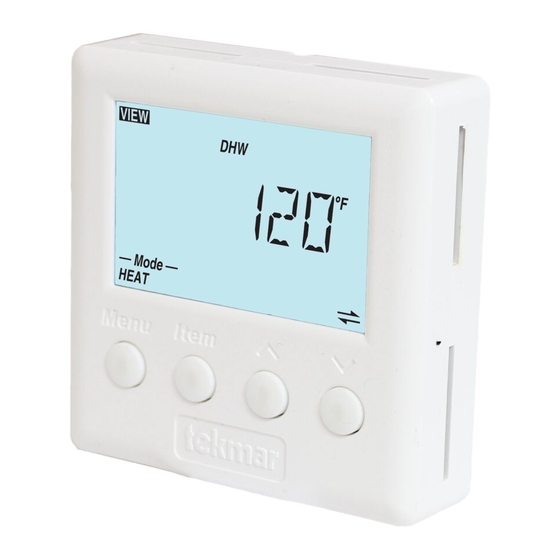
4 Setpoint Control 161
The following brochure describes how to wire the
tekmarNet
single output for heat. The 161 has one sensor input.
24 V (ac) Power
Definitions .......................................................................2
Rough-In Wiring .............................................................2
Remove the Wiring Cover ...............................................3
Mounting the Setpoint Control ........................................3
Wiring Symbols ...............................................................4
Electrical Drawings .........................................................4
Wiring the Setpoint Control .............................................7
Troubleshooting the Wiring .............................................9
Testing the Wiring ......................................................... 10
Technical Data .............................................................. 12
4 (tN4) Setpoint Control 161. The 161 has a
®
tN4 Network
Sensor Input
Table of Contents
W 161
Jumper
tN4 Setpoint Control 161
One Stage Heat
Power:
24 V ±10% 50/60 Hz 1.7 VA
Relays:
24 V (ac) 2 A
/
DIP
Switches
© 2008
W 161 - 12/08
12/08
Relay
Contact
Cut jumper to
isolate relay
Feb 2006
Lot 1948
Meets Class B:
Canadian ICES
FCC Part 15
161
Advertisement
Table of Contents

Related Manuals for Tekmar tekmarNet 4 Setpoint Control 161


Summary of Contents for Tekmar tekmarNet 4 Setpoint Control 161
-
Page 1: Table Of Contents
W 161 Wiring Brochure tekmarNet ® 4 Setpoint Control 161 12/08 Overview The following brochure describes how to wire the Information tekmarNet 4 (tN4) Setpoint Control 161. The 161 has a ® Brochure single output for heat. The 161 has one sensor input. Choose controls to match Relay... -
Page 2: Installation Of
Defi nitions The following defined terms and symbols are used throughout this manual to bring attention to the presence of hazards of various risk levels, or to important information concerning the life of the product. – Caution: Refer to accompanying documents. –... -
Page 3: Remove The Wiring Cover
Note: When multiple wires 2 Cond. / 18 AWG Sensor run to the same equipment location, wiring conductors can share one wire jacket. Pump 2 Cond. / 18 AWG Valve 3 Cond. / 18 AWG Zone Manager Remove the Wiring Cover To remove the wiring cover: •... -
Page 4: Wiring Symbols
If a switch box was not used, mount the control directly to the wall. • Feed the wiring through the openings in the back of the control. • Use screws in the screw holes to fasten the control to the wall. At least one of the screws should enter a wall stud or similar rigid material. - Page 5 Electrical Application 161 E1 Description: Setpoint Control used with tN4 System Zone Manager. For product instructions see brochure Use at least 194°F (90°C) conductors Sensor Heat Zone Zone Manager Zone Pump Valve 5 of 12 © 2008 W 161 - 12/08...
- Page 6 Electrical Application 161 E2 Description: Setpoint Control used as a stand alone device. Relay 1 is used to cycle a pump to provide heat. Legend: P1 = Pump cycled for heating Relay 003 For product instructions see brochure Use at least 194°F (90°C) conductors Sensor External Class 2 Transformer...
-
Page 7: Job Wiring The Setpoint Control
Wiring the Setpoint Control Power 24 V (ac) Terminals 2, 3 Wire 24 V (ac) to terminals C and R. If a Zone Manager is used: • Connect C on the setpoint control to C on the proper zone of the Zone Manager. •... - Page 8 Relay 1 Terminals 6, 7 Relay 1 is used to switch the heat. If a Zone Manager is used: • Connect Relay 1 to W on the proper zone on the Zone Manager. If a Zone Manager is not used: •...
-
Page 9: Troubleshooting The Wiring
Troubleshooting the Wiring General The following tests are to be performed using standard testing practices and procedures and should only be carried out by properly trained and experienced persons. A good quality electrical test meter, capable of reading from at least 0 - 300 V (ac), 0 - 2,000,000 Ohms, and testing for continuity is essential to properly test the wiring and sensors. -
Page 10: Testing The Wiring
Testing the Wiring Testing 24 V (ac) Power Supply 1. Remove the front cover from the setpoint control. 2. Use an electrical test meter to measure (ac) voltage between the R and C terminals. The reading should be 24 V (ac) +/– 10%. 3. - Page 11 Testing the Sensor To test the sensor, the actual temperature at the sensor location must be measured. Use a good quality digital thermometer with a surface temperature probe for ease of use and accuracy. Where a digital thermometer is not available, place a spare sensor alongside the one to be tested and compare the readings.
-
Page 12: Technical Data
NTC thermistor, 10 k @ 77°F (25°C ± 0.2°C) ß = 3892 – Included Universal Sensor 071 – Optional tekmar type #070, 071, 072, 073, 076, 077, 078, 079, 082, 083, 084 The installer must ensure that this control and its wiring are isolated and / or shielded from strong sources of electromagnetic noise.
Need help?
Do you have a question about the tekmarNet 4 Setpoint Control 161 and is the answer not in the manual?
Questions and answers