Table of Contents
Advertisement
Quick Links
Advertisement
Table of Contents

Related Manuals for multicomp pro HDS-N Series


Summary of Contents for multicomp pro HDS-N Series
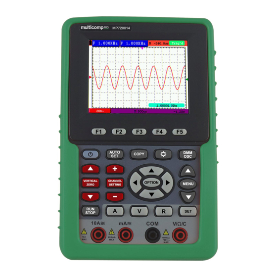
- Page 1 Handheld Storage Oscilloscope Model MP720014 and MP720015...
-
Page 2: Table Of Contents
Table of Contents 1.2 PACKAGE CONTENTS ·················································· 5 2. SAFETY INFORMATION ·················································· 6 2.1 Safety Symbols and Terms ·············································································· 6 2.1.1 Safety Symbols ····················································································· 6 2.1.2 Safety Terms ························································································· 6 2.2 General Safety Information ············································································ 6 3. GENERAL CHARACTERISTICS······································· 9 4. - Page 3 6.13 Using Persistence to Display Waveforms ··························································23 6.14 Using Peak Detection to Display Glitches ·························································24 6.15 Selecting AC-coupling ·················································································25 6.16 Reversing the Polarity of the Displayed Waveform ·············································26 6.17 Use USB mass storage device to save waveform data ··················································26 7. USING THE MULTIMETER ············································ 32 7.1 About this Chapter ······················································································32 7.2 Making Meter Connections ············································································32 7.3 Multimeter Operation Window ·······································································32...
- Page 4 8.9 Making Automatic Measurements ···································································55 8.10 Setting the Cursor Measurements ··································································56 8.10.1 Setting the cursor measurement in normal mode ··············································56 8.10.2 Setting the cursor measurement in FFT mode ··················································59 8.11 Autoscale ·································································································60 8.12 Record ····································································································61 8.13 Using FFT ································································································64 8.14 System State Menu ·····················································································70 8.14.1 Real time clock ···················································································71 8.15 Setting of Time Base Mode ···········································································71 8.16 Data Transmission ······················································································73...
-
Page 5: Package Contents
1.2 Package Contents See the picture below. This picture is only for your reference. If any discrepancy found between certain picture and product, please look the actual product. Description Standard Optional Oscilloscope and Battery ● AC-DC adapter ● Oscilloscope Probe × 1 (grey) ●... -
Page 6: Safety Information
2-Safety information 2. Safety Information In order to ensure the correct using and the best efficient service, please carefully read this user's manual. 2.1 Safety Symbols and Terms 2.1.1 Safety Symbols These symbols may appear in this manual or on the instrument. Warning: "Warning"... - Page 7 2-Safety information Warning: To avoid fire or electrical shock, please use proper power adapter. Use only the power adapter appointed by the manufacturer and subject to approval of being used in the user's country. Warning: The two channels of the oscilloscope are non-isolated electrically. The channels should adopt common basis during measuring.
- Page 8 2-Safety information ● Always connect the power adapter first to the AC outlet before connecting it to the Oscilloscope & Multimeter. ● Do not apply voltages that differ more than 400 V from earth ground to any input when measuring in a CAT Ⅱ environment. ●...
-
Page 9: General Characteristics
3-General Characteristics 3. General Characteristics Oscilloscope 2 in 1 (Multimeter function support); Record length of 6,000 points for each channel; Reading-out with the cursor; Eighteen automatic measurement functions; Autoscale function; Colour liquid crystal display of high resolution and high contrast with ... -
Page 10: Performing The General Inspection
4-Performing the General Inspection 4. Performing the General Inspection 4.1 Performing the General Inspection When you have got a new oscilloscope, it is suggested that you should perform a general inspection on the instrument according to the following steps. 4.1.1 Check whether there is any Damage on it Due to Transportation If the packing boxes or foam cushions are found to have serious damage, keep them in a safe place until the complete instrument and accessories have passed the electrical and mechanical tests. -
Page 11: Input Connections
5-Input Connections 5. Input Connections 5.1 Input Connections 5.1.1 Input connections See the following Figure 2: Figure 2:Input connections Description: 1. The power adapter is supplied for AC power supply and battery recharging. 2. Multimeter test lead. 3. Multimeter input jacks, including four circular banana jacks. The first jack measuring the current 2A-10A, the second jack on the current Measurement, the third COM ground input, and the fourth measuring voltage, resistance, Capacitance input. -
Page 12: The Connection Of 1 Khz/5 V Square-Wave Test Signal
5-Input Connections 5.1.2 The connection of 1 kHz/5 V Square-wave test signal At the left side of the oscilloscope, it is a port for testing 1 kHz/5 V square-wave signal which is used to adjust the probe, shown as Fig.3 Fig.3. - Page 13 5-Input Connections Figure 4:Front Panel Description: 1. AC adapter Port 2. RS-232C Port. 3. USB Port. 4. USB Mass Storage Port. 5. Power switch. 6. F1 - F5: Switch or Adjust options for each menu.
- Page 14 5-Input Connections 7. AUTO SET: Under DSO mode, automatically selects the horizontal scales, vertical scale, and trigger level according to the input signal. 8. COPY: Press to save the waveform data into the USB Mass Storage Device. 9. ▲ (red): Adjust vertical position in Channel. 10.
-
Page 15: Using The Oscilloscope
6-Using the Oscilloscope 6. Using the Oscilloscope 6.1 About this Chapter This chapter provides a step-by-step introduction to the scope functions. The introduction does not cover all of the capabilities of the scope functions but gives basic examples to show how to use the menus and perform basic operations. - Page 16 6-Using the Oscilloscope Description: Battery electric quantity indicating symbols. Auto measurement window 1, in which "F "means frequency, "T" means cycle, "V" means the average value, "Vp" the peak-peak value ,"Vr" the root-mean-square value,. "Ma" the maximum amplitude value, "Mi" the minimum amplitude value, "Vt" the Voltage value of the waveform's flat top value, "Vb"...
-
Page 17: Menu Description
6-Using the Oscilloscope 14. OPTION operation prompt: There are different prompts for different OPTION operations. 15. Waveform display area, and the wave shows red. 6.4 Menu Description The following example shows how to use the tool's menus to select a function, as shown in the following figure. -
Page 18: Setting The Horizontal System And Trigger Position
6-Using the Oscilloscope 6.5.2 Setting the Horizontal System and Trigger Position OPTION key is a multiple setting key to set trigger vertical position, main time base and horizontal position (trigger horizontal position) during edge trigger and video trigger. The following example shows how to use OPTION key to make a setting. The following guidance is for the operation on the mode of edge triggering and video triggering. -
Page 19: Recall Factory Settings
6-Using the Oscilloscope Figure 8 4. Press ◄( OPTION) or ►( OPTION) to adjust time base horizontal position, press V key to "zero" the horizontal position; press ▲(OPTION) or ▼(OPTION) to adjust trigger level position, press R key to "zero" the trigger level position. 5. -
Page 20: Input Connections
6-Using the Oscilloscope 3. Press F1 key to select "Recall Factory" to recall the factory settings. 4. Press F2 key to select "Auto calibration". If the ambient temperature variation is up to or larger than 5 Celsius degree, the Auto calibration function should be performed. But this will not affect the using and capability by the heat from LCD and electronic component See the following Figure 9: Figure 9: Reset the Oscilloscope... -
Page 21: Automatic Measurements
6-Using the Oscilloscope 6.9 Automatic Zero-returning of Trigger Horizontal Position and Trigger Level Position When we adjust the trigger horizontal position and trigger level position to be maximal to make it off the screen center remotely, then we perform the following steps to make trigger horizontal position and trigger level position return to zero automatically. -
Page 22: Freezing The Screen
6-Using the Oscilloscope Figure 10: Automatic Scope Measurements 6.11 Freezing the Screen You can freeze the screen (all readings and waveforms) Press the RUN/STOP key to freeze the screen and STOP appears at top right side of the screen. Press the RUN/STOP key once more to resume your measurement. See the following figure 11: Figure 11: Freezing the Screen 6.12 Using Average for Smoothing Waveforms... -
Page 23: Using Persistence To Display Waveforms
6-Using the Oscilloscope number of averaging increases, the slower the waveform update becomes. Press the MENU key and the function menu appears on the right side of the screen. Press MENU ▲ or MENU ▼ key to select ACQU MODE, with four items selectable displayed at the bottom of the screen. -
Page 24: Using Peak Detection To Display Glitches
6-Using the Oscilloscope Figure 13: Persistence to Observe Dynamic Signals 6.14 Using Peak Detection to Display Glitches You can use this function to display events (glitches or other asynchronous waveforms) of 50 ns or wider. Press MENU key and the function menu appear at the right side of the screen. Press MENU ▲... -
Page 25: Selecting Ac-Coupling
6-Using the Oscilloscope Collecting mode: The oscilloscope transforms the collected analog data into a digital form after they are gathered in the following three different modes, that is, sampling, peak value detection and averaging values. Sampling: The oscilloscope takes samples from the signal at a equal time interval to reconstruct the waveform in this mode, by which the analog signal can be expressed correctly in most cases, yet, the rapid changes can not be collected between two sampling time intervals, causing the confusion and loss the narrow pulse in the signal probably. -
Page 26: Reversing The Polarity Of The Displayed Waveform
6-Using the Oscilloscope Figure 15: AC-Coupling 6.16 Reversing the Polarity of the Displayed Waveform To invert the input waveform, do the following: Press the MENU key and the function menu appears at the right side of the screen. Press the MENU ▲ or MENU ▼ key to select CH SETUP. Four items selectable are displayed at the bottom of the screen. - Page 27 6-Using the Oscilloscope waveform data will be saved into the USB mass. The save waveform has two format, one is vector format and the other is bitmap format, according to the display settings from the choice of the communication settings. Name the file with current date and suffix by .bin or .bmp. Then connect the USB mass storage device with the computer after data is saved, and open the data of vector format with the analysis software, or direct open the bitmap.
- Page 28 6-Using the Oscilloscope 4. Right click 1 or 2 red mark area, choose Format. And system will pop up a warning message, click Yes. Format the USB disk warning 5. Set File System as FAT32, Allocation unit size 4096. Check "Perform a quick format"...
- Page 29 6-Using the Oscilloscope Formatting the USB disk Check whether the USB disk is FAT32 with allocation unit size 4096 after formatting. Use Minitool Partition Wizard to format Download URL: http://www.partitionwizard.com/free-partition-manager.html Tip: There are many tools for the USB disk formatting on the market, just take Minitool Partition Wizard for example here.
- Page 30 6-Using the Oscilloscope Reload Disk 4. Right click 1 or 2 red mark area, choose Format. Choose format 5. Set File System FAT32, Cluster size 4096. Click OK. Format setting 6. Click Apply at the top left of the menu. Then click Yes on the pop-up warning to begin formatting.
- Page 31 6-Using the Oscilloscope Apply setting 7. Formatting process Format process Format the USB disk successfully Format successfully...
-
Page 32: Using The Multimeter
7-Using the Multimeter 7. Using the Multimeter 7.1 About this Chapter This chapter provides a step-by-step introduction to the multi-meter functions of the test tool hereafter. The introduction gives basic examples to show how to use the menus and perform basic operations. -
Page 33: Making Multimeter Measurements
7-Using the Multimeter Measurement mode indicators: DCV: Direct voltage measurement ACV: Alternating voltage measurement DCA: Direct current measurement ACA: Alternating current measurement R: Resistance measurement : Diode measurement : On/Off measurement C: Capacitance measurement The relative magnitude measurement indicator. Running state indicators, among which RUN expresses continuous update and STOP represents the screen locking. -
Page 34: Measuring Diode
7-Using the Multimeter Insert the black lead into the COM banana jack input and the red lead into the V/Ω/C banana jack input. Connect the red and black test leads to the resistor. The resistor value readings are shown on the screen in Ohm. -
Page 35: On-Off Test
7-Using the Multimeter Figure 19: Diode Measurement 7.4.3 On-off Test To perform an On-off test, do the following: Press the R key and R appears on the top of the screen. Press the SET key until the following is shown on the screen. Insert the black lead into the COM banana jack input and the red lead into the V/Ω/C banana jack input. -
Page 36: Measuring Dc Voltage
7-Using the Multimeter Press the R key and R appears on the top of the screen Press the SET key until C appears at the top of the screen. Insert the capacitance measurer of this multimeter to COM jack and V/Ω/C jack. Insert the capacitance to the capacitance measurer, then screen shows the capacitance reading. -
Page 37: Measuring Ac Voltage
7-Using the Multimeter Figure 22: DC Voltage Measurement 7.4.6 Measuring AC Voltage To measure the AC voltage, do the following: Press the V key and DCV appears at the top of the screen. Press the SET key and ACV appears at the top of the screen. Insert the black lead into the COM banana jack input and the red lead into the V/Ω/C banana jack input. -
Page 38: Measuring Dc Current
7-Using the Multimeter 7.4.7 Measuring DC Current To measure a DC current which is less than 400 mA, do the following: Press the A key and DCA appears at the top of the screen. The unit on the main reading screen is mA. -
Page 39: Measuring Ac Current
7-Using the Multimeter Figure 25: DC Current Measurement for 10A 7.4.8 Measuring AC Current To measure an AC current which is less than 400 mA, do the following: Press the A key and DCA appears at the top of the screen. The unit on the main reading screen is mA. -
Page 40: Freezing The Readings
7-Using the Multimeter To measure an AC current which is larger than 400 mA, do the following: Press the A key, an instruction prompt you to plug the multimeter test leads in the right position. After check, press any key to enter into multimeter measure and DCA appears at the top of the screen. -
Page 41: Taking A Relative Measurement
7-Using the Multimeter Figure 28: Freezing the Readings 7.6 Taking a Relative Measurement A currently measured result relative to the defined reference value is displayed in a relative measurement. The following example shows how to take a relative measurement. At first, it is required to acquire a reference value. -
Page 42: Selecting Automatic/Manualrange Adjustment
7-Using the Multimeter Figure 29: Relative Measurement 7.7 Selecting Automatic/ManualRange Adjustment The defaulted range mode of the instrument is automatic range. To switch to the manual range, perform the following steps: Press F1 key and MANUAL is displayed on the top left side of the screen to enter the manual range mode. -
Page 43: Advanced Function Of Oscilloscope
8-Advanced Function of Oscilloscope 8. Advanced Oscilloscope Function 8.1 About this Chapter This chapter will detail the oscilloscope function of the test tool. 8.2 Setting the Vertical Channel Each channel has its own independent vertical menu and each item can be set respectively based on the specific channel. -
Page 44: Setting The Channel Coupling
8-Advanced Function of Oscilloscope The following Table describes the Vertical Channel menu: Function menu Setting Description The dc component in the input signal is blocked. Coupling The ac and dc components of the input signal are allowed. Ground Input signal is interrupted. Close the channel. -
Page 45: Open And Close Settings On Channel
8-Advanced Function of Oscilloscope Figure 33: DC Coupling Figure 34: Ground Coupling 8.2.2 Open and Close Settings on Channel Press F2 Channel key first, and then OFF to make a Close setting on channle. Press F2 Channel key first, and then ON to make an Open setting on channle. 8.2.3 Setting the probe attenuation To prevent excessive input voltage, we recommend you to set the probe attenuation level to the 10X position to prevent excessive voltage. -
Page 46: Setting Of Inverted Waveform
8-Advanced Function of Oscilloscope Table: Probe attenuation level and the corresponding menu setting Probe attenuation level Corresponding Menu Setting 10:1 10 X 100:1 100 X 1000:1 1000 X 8.2.4 Setting of Inverted Waveform Inverted waveform: The displayed signal reverses 180 degrees relatively to the ground potential. Press F4 to set Inverted as ON to start Invert;... -
Page 47: Edge Trigger
8-Advanced Function of Oscilloscope Video trigger: Perform video field trigger or line trigger on the standard video signals. The following describes Edge trigger and Video trigger menus respectively. 8.4.1 Edge Trigger The Edge trigger is a mode by which trigger occurs at the triggering threshold value of the input signal edge. - Page 48 8-Advanced Function of Oscilloscope Figure 36: Video Odd Field Trigger Designed Designed Figure 37: Video Line trigger (Page1) Figure 38: Video Line trigger (Page2) The Video trigger menu is described in the following table (First page): Function menu Settings Description Line Make a video line trigger synchronization setting.
- Page 49 8-Advanced Function of Oscilloscope 2. when the sync is Line NUM, the second page menu is shown as bellow. Increase Set the line value to increase Line Decrease Set the line value to decrease Line No. Set and Show the line valve -->...
-
Page 50: Setting The Acquiring Mode
8-Advanced Function of Oscilloscope specified period of time without any triggering condition ignited. When an invalid trigger is enforced,the oscilloscope can not keep the waveform in phase. Normal trigger mode: In this mode, the oscilloscope cannot acquire the waveform until it is triggered. -
Page 51: Display Style
8-Advanced Function of Oscilloscope 8.6.1 Display Style The display style includes Vectors and Dots displays, shown as the following figure 40, figure 41. Figure 40: Dots Style Figure 41: Vectors Style 8.6.2 Persistence With Persist function selected, the displayed saved original data gradually decay in colour and the new data are bright in colour;... -
Page 52: Waveform Saving Setups
8-Advanced Function of Oscilloscope If you want to measure frequency of the Channel, you can do as the follows: Press MENU, the function menu will appear on the right of the screen. Press MENU ▲ or MENU ▼ and choose DISP SET, five options will show at the bottom of the screen. -
Page 53: Waveform Saving Setups In Fft Mode
8-Advanced Function of Oscilloscope Press the F1 key to select the address A. Press the F2 key to save the waveform in address A. To display the saved waveform on the screen, do the following: 6. Press the F3 key to select ON for the address A. The waveform saved in address A will be displayed on the screen in green colour. -
Page 54: Function Setting Menu
8-Advanced Function of Oscilloscope To display the saved waveform on the screen, do the following: Press the F3 key to select ON for the address A. The waveform saved in address A will be displayed on the screen in green colour and the zero point of waveform, Vamp and Freq is purple. -
Page 55: Making Automatic Measurements
8-Advanced Function of Oscilloscope 3. After removing all cables, press F2 (Auto calibration) again. The Auto-calibration automatically starts and a message appears, showing that the calibration is ongoing. To interrupt calibration, press any key during the calibration. 8.9 Making Automatic Measurements The oscilloscope can perform 18 types automatic measurements such as frequency, cycle, average value, peak-to-peak value , root mean square value, Vmax, Vmin, Vtop, Vbase, Vamp, Overshoot, Preshoot, Rise Time, Fall Time, +Width, -Width, +Duty, -Duty;... -
Page 56: Setting The Cursor Measurements
8-Advanced Function of Oscilloscope Press the F4 key to jump to the PK-PK measurement. The measurement window on the screen shows the peak-to-peak value of waveform. Now, you can see a screen that looks like the following figure 45. Figure 45: Automatic Measurements 8.10 Setting the Cursor Measurements This oscilloscope allows you to make manual cursor measurements on time and voltage. - Page 57 8-Advanced Function of Oscilloscope Press F1 key to select the measurement type Voltage. Two purple crossing dashed lines V1 and V2 are shown on the screen. Press OPTION and display as —Cursor 1 —Cursor 2 When setting OPTION ▲ or OPTION ▼, V2 will move up and down and the relating voltage value to the zero position of Channel 1 will show at the bottom of the screen.
- Page 58 8-Advanced Function of Oscilloscope To use the cursor for a time measurement, do the following: Press the MENU key and the function menus are displayed at the right of the screen. Press the MENU ▲ or MENU ▼ key to select CURS MEAS. Press the F1 key to select the measurement type as Time.
-
Page 59: Setting The Cursor Measurement In Fft Mode
8-Advanced Function of Oscilloscope Figure 49: Use the Cursor for a Time Measurement 8.10.2 Setting the cursor measurement in FFT mode FFT being on, the cursor measurement menus are listed and described in the following table. Function menus Settings Description Close the cursor measurement. -
Page 60: Autoscale
8-Advanced Function of Oscilloscope Figure 50: Cursor range measurement 8.11 Autoscale The function is applied to follow-up signals automatically even if the signals change at any time. Autoscale enables the instrument to set up trigger mode, voltage division and time scale automatically according to the type, amplitude and frequency of the signals. -
Page 61: Record
8-Advanced Function of Oscilloscope Press F2 and choose HORI -VERT. Press F3 and displays on the screen as figure 51: Figure 51: Autoscale Horizontal- Vertical multi-period waveforms Note: Things you should be ware when turning on Autoscale. 1. The symbol is flickering on the top left corner of screen every half second. - Page 62 8-Advanced Function of Oscilloscope through Playback and Save functions. Four record modes: Record, Play back, Storage, OFF. Record:Record the waveforms up until the set number of frames at specified time intervals. Record menu list: Menu Setting Instruction Record Select record mode. Play back Select play back mode.
- Page 63 8-Advanced Function of Oscilloscope --> To next menu Start Frame 1-1000 Set start frame. Select current frame to be played. Cur frame 1-1000 End frame 1-1000 Set End frame. Increase The value increases at the mode of setting start frame, cur frame and end frame Direction Decrease...
-
Page 64: Using Fft
8-Advanced Function of Oscilloscope Press F1 and select OFF to stop refreshing waveforms. Press F5 to back up to the first menu. Press F3 and select Play to operate. Shown as Fig.52 and Fig.53 Fig.52:the first page of the record Fig.53: the second page of the record 8.13 Using FFT An FFT breaks down signals into component frequencies, which the oscilloscope uses to display a... - Page 65 8-Advanced Function of Oscilloscope components and the final frequency contains 1024 points ranging from 0Hz to Nyquist frequency. The following table describes the FFT menu: Function Menu Setting Instruction Turn on FFT function Turn off FFT function Rectangle Blackman Select window for FFT. Window Hanning Hamming...
- Page 66 8-Advanced Function of Oscilloscope ▲/▼ If left bottom of the screen displays " —FFT dB Scale ", press (red) (red) button to adjust dB value of each DIV, including 1dB, 2dB, 5dB, 10dB, 20dB; ▲/▼ If left bottom of the screen displays " —CH Volts/Div "...
- Page 67 8-Advanced Function of Oscilloscope Figure 54 The Shown Frequency of M Selecting an FFT Window The FFT feature provides four windows. Each is a trade-off between frequency ■ resolution and magnitude accuracy. What you want to measure and your source signal characteristics help determine which window to use.
- Page 68 8-Advanced Function of Oscilloscope This is a very good window for measuring amplitude accuracy but less so for resolving frequencies. Hanning Use Hanning for measuring sine, periodic and narrow band random noise. This window works on transients or bursts where the signal levels before and after the event are significantly different.
- Page 69 8-Advanced Function of Oscilloscope Fig.57. Hanning window window Fig.58. Hamming Quick Tips If desired, use the zoom feature to magnify the FFT waveform. Use the default dB scale to see a detailed view of multiple frequencies, even if they have very ...
-
Page 70: System State Menu
8-Advanced Function of Oscilloscope is exactly half of the sampling rate under the condition of no mistakes, which is called Nyquist frequency. If under-sampling occurs when the frequency sampled is higher than Nyquist frequency, "False Wave" phenomenon will appear. So pay more attention to the relation between the frequency being sampled and measured. -
Page 71: Real Time Clock
8-Advanced Function of Oscilloscope 8.14.1 Real time clock Function: Be synchronous with the U disk storage time. Do below steps to set up the real time clock: 1. Press MENU key and the function menu is displayed on the right side of the screen. 2. - Page 72 8-Advanced Function of Oscilloscope Press MENU key, display the function menu on the right side of the screen. Press MENU ▲ or MENU ▼ key to select TIME MODE, display three options at the bottom. Zone Window Press F2 key to select Press OPTION key to pop up TIME BASE, at this time, then press ◄...
-
Page 73: Data Transmission
8-Advanced Function of Oscilloscope 8.16 Data Transmission For the operation of data transmission, please execute the following steps: Press MENU key, display the function menu on the right side of the screen. Press MENU ▲ or MENU ▼ key to select DISP SET. Press F4 key, select the Bitmap or Vectors for data transmission. - Page 74 8-Advanced Function of Oscilloscope On running the PC oscilloscope software, a valid connection between the oscilloscope and the PC is indicated in green on the bottom right hand corner of the screen.
-
Page 75: Trouble Shooting
Trouble Shooting 9. Trouble Shooting 1. The oscilloscope does not power up It may be caused by the dead battery. At this time, the oscilloscope will not start even if it is powered by the battery charger. Firstly, charge the battery and supply the oscilloscope with power through the battery charger. -
Page 76: Appendix
Only if other instructions are provided, are all technical specifications applicable to the probe with the 10X attenuation switch setting and the HDS-N series digital type oscilloscope. In order to be up to these specifications, the oscilloscope should meet the following requirement. - Page 77 10-Appendix Sampling rate and delay ±100ppm time accuracy (any time interval which is equal to or larger than 1ms) Single: Time interval △ ±(1 sampling interval time +100ppm×reading+0.6ns) T)measurement accuracy >average 16 : (full bandwidth) ±(1 sampling interval time +100ppm×reading+0.4ns) Vertical Analog digital...
-
Page 78: Meter
10-Appendix Cymometer Signal system and line/field Support the NTSC, PAL and SECAM broadcasting systems frequency (Video triggering mode) of any field or line frequency. Readout resolution 6 digits Frequency range AC coupling, 2 Hz to full bandwidth When the triggering mode is edge triggering, it is a one ... - Page 79 10-Appendix Voltage (VAC) Input Impedance: 10 MΩ Max Input Voltage: 750 V (AC, RMS value) Frequency range: from 40 Hz to 400 Hz Display: RMS value of the sine wave Range Accuracy Resolution 4.000 V 1 mV 40.00 V ±1%±3 digits 10 mV 400.0 V 100 mV...
-
Page 80: General Specifications
10-Appendix 10.1.3 General Specifications Basic parameter Mechanical dimension 18 cm×11.5 cm×4 cm Weight 645 g Power consumption < 6 W Display type 3.7" colour liquid crystal display Display resolution 640 (horizontal) ×480 (vertical) pixels Display colour 65536 colours Power Adapter Power supply 100 - 240 V AC 50/60Hz Voltage output... -
Page 81: Appendix B: Maintenance And Cleaning
10-Appendix 10.2 Appendix B: Maintenance and Cleaning 10.2.1 Maintenance Do not store or place the instrument in locations where the liquid crystal display (LCD) may be directly exposed to the sunshine for long periods. Be careful: Do not spray liquid into the instrument. Cleaning To clean the instrument exterior, perform the following steps: Wipe the dust from the instrument surface with a soft cloth. -
Page 82: Replacing The Lithium Battery Unit
10-Appendix 10.2.3 Replacing the Lithium Battery Unit It is usually not required to replace the battery unit, but if it is required to replace it, only qualified personnel can carry out this operation, and only use the same specification lithium battery. INFORMATION ON WASTE DISPOSAL FOR CONSUMERS OF ELECTRICAL &...
Need help?
Do you have a question about the HDS-N Series and is the answer not in the manual?
Questions and answers