Table of Contents
Advertisement
Quick Links
Advertisement
Table of Contents

Related Manuals for multicomp pro MP700005


Summary of Contents for multicomp pro MP700005
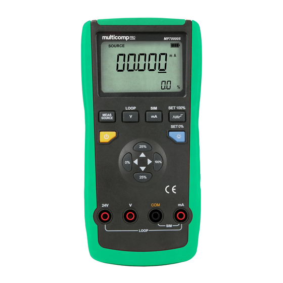
- Page 1 Loop Calibrator Model No. MP700005...
-
Page 2: Important Safety Information
IMPORTANT SAFETY INFORMATION Read all instructions before using the appliance and retain for future reference. • Please follow all safety operation instructions. • Check the test leads, probes and case insulation before using. If you find any breakage or abnormality, or you consider the device is broken, stop using the device immediately. - Page 3 Measure/Source Mode button Voltage/Current Mode button mA current selection button SLOPE/STEP mode button Power ON/OFF button Backlight/Current to 0% button 0% Value Setting button +25%Value Setting button 100%Value Setting button 10. -25% Value Setting button 11. Test lead connection terminals FUNCTIONS Source •...
- Page 4 Auto Power Off • The calibrator will automatically shut down if there is no button or communication operation within the 30min (factory setting), which is enabled by default and is displayed for about 2s during the booting process. • To disable auto power off, press down LEFT (0%) value button while turning on the calibrator until the buzzer beeps.
-
Page 5: Operation
OPERATION Voltage Measurement • Short press MEASURE/SOURCE and select Measure, then press V and the LCD displays ‘V’ unit. • Connect the red test lead to V terminal, black to COM terminal. • Connect the test probes to the voltage points to be tested: connect the red probe to the positive terminal, black to negative terminal. - Page 6 Loop Current Measurement with Loop Power • The loop power function activates a 24V power supply in series with the current measuring circuit inside the calibrator, allowing you to test the transmitter out of the field power supply of the 2-wire transmitter. •...
- Page 7 Current Source Output • Press MEASURE/SOURCE button to select the source function and the LCD will display ‘SOURCE’. • Press mA button and ‘mA’ is displayed on the LCD. • Connect the red test lead to mV terminal, black to COM terminal. •...
- Page 8 Simulating Transmitter • Simulating the 2-wire transmitter is a special operation mode in which the calibrator is connected to the application loop instead of the transmitter, and provides a known and configurable test current. The steps are as follows: • Press MEASURE/SOURCE button to select the source function and the LCD will display ‘SOURCE’.
-
Page 9: Advanced Applications
ADVANCED APPLICATIONS Setting 0% and 100% Output Parameters • Users need to set the values of 0% and 100% for the step operation and percentage display. Some values of the calibrator have been set as default. • The table below lists the factory settings. Output Functions 0% value 100% Value... -
Page 10: Specifications
SPECIFICATIONS • All specifications are based on a one year calibration period and applied to a working temperature range of +18 C~+28 C unless otherwise specified. All specifications are obtained after a 30 minute period of operation. Max voltage between any terminal and ground or between any two terminals: 30V Range: manual Operating temperature:... -
Page 11: Maintenance
MAINTENANCE Warning: Before opening the rear cover or the battery cover, power the instrument down and remove the test leads from any device or circuit under test and remove the test leads from the input terminals • If the low battery symbol illuminates on the LCD, this indicates that the battery power is less than 20%. - Page 12 INFORMATION ON WASTE DISPOSAL FOR CONSUMERS OF ELECTRICAL & ELECTRONIC EQUIPMENT. These symbols indicate that separate collection of Waste Electrical and Electronic Equipment (WEEE) or waste batteries is required. Do not dispose of these items with general household waste. Separate for the treatment, recovery and recycling of the materials used. Waste batteries can be returned to any waste battery recycling point which are provided by most battery retailers.
Need help?
Do you have a question about the MP700005 and is the answer not in the manual?
Questions and answers