Table of Contents
Advertisement
Quick Links
Advertisement
Table of Contents

Subscribe to Our Youtube Channel
Related Manuals for multicomp pro MP720854


Summary of Contents for multicomp pro MP720854
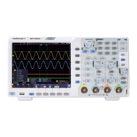
- Page 1 MP720854 Four-Channel Series Digital Storage Oscilloscopes User Manual...
-
Page 2: Table Of Contents
Table of Contents 1. General Safety Requirements ..................1 2. Safety Terms and Symbols ....................2 3. Junior User Guidebook ....................4 Introduction to the Structure of the Oscilloscope ..............5 Front Panel ............................... 5 Rear Panel ..............................6 Control Area ............................. 7 User Interface Introduction ...................... - Page 3 How to Set the Display System ......................59 How to Save and Recall a Waveform ..................... 62 How to Record/Playback Waveforms ....................69 How to Clone and Recall a waveform ....................73 How to Implement the Auxiliary System Function Setting ..............78 How to Update your Instrument Firmware .....................
-
Page 4: General Safety Requirements
Multicomp-pro 1. General Safety Requirements Before use, please read the following safety precautions to avoid any possible bodily injury and to prevent this product or any other connected products from damage. In order to avoid any contingent danger, ensure this product is only used within the range specified. -
Page 5: Safety Terms And Symbols
Multicomp-pro 2. Safety Terms and Symbols Safety Terms Terms in this manual. The following terms may appear in this manual: Warning: Warning indicates the conditions or practices that could result in injury or loss of life. Caution: Caution indicates the conditions or practices that could result in damage to this product or other property. - Page 6 Multicomp-pro The diagram of the oscilloscope ground wire connection: Probe Oscilloscope Electrical Outlet Signal Input Power Cord Ground Clip The diagram of the ground wire connection when the battery-powered oscilloscope is connected to the AC-powered PC through the ports: Oscilloscope Probe Electrical Outlet (Battery-power)
-
Page 7: Junior User Guidebook
Multicomp-pro 3. Junior User Guidebook This chapter deals with the following topics mainly: Introduction to the structure of the oscilloscope Introduction to the user interface How to implement the general inspection How to implement the function inspection ... -
Page 8: Introduction To The Structure Of The Oscilloscope
Multicomp-pro Introduction to the Structure of the Oscilloscope This chapter makes a simple description of the operation and function of the front panel of the oscilloscope, enabling you to be familiar with the use of the oscilloscope in the shortest time. Front Panel The front panel has controls and function buttons. -
Page 9: Rear Panel
Multicomp-pro 9. USB Host port: It is used to transfer data when external USB equipment connects to the oscilloscope regarded as "host device". For example: Saving the waveform to USB flash disk needs to use this port. 10. Power on/off Rear Panel Figure 3-2 Rear Panel 1. -
Page 10: Control Area
Multicomp-pro Control Area Figure 3-3 Control Area Overview 1. Function button area: Total 11 buttons 2. Waveform generator controls (optional) DAQ: Multimeter Recorder (see "Multimeter Recorder" on PError! Bookmark not defined.) P/F: Pass/Fail (see "Pass/Fail" on P79) W.REC: Waveform Record (see "How to Record/Playback Waveforms" on P69) 3. -
Page 11: User Interface Introduction
Multicomp-pro it to close the menu on the left and right. User Interface Introduction Figure 3-4 Illustrative Drawing of Display Interfaces 1. Waveform Display Area. 2. Run/Stop (touchable on touchscreen) (see "How to Use Executive Buttons" on P92) 3. The state of trigger, including: Auto: Automatic mode and acquire waveform without triggering. - Page 12 Multicomp-pro (only for touchscreen). 10. It shows setting time (see "Config" on P78). 11. It indicates that there is a USB disk connecting with the oscilloscope. 12. Indicating battery power status (see "Display" on P78). 13. The waveform of CH1. 14.
-
Page 13: How To Implement The General Inspection
Multicomp-pro 30. The blue pointer indicates the grounding datum point (zero point position) of the waveform of the CH1 channel. 31. The yellow pointer indicates the grounding datum point (zero point position) of the waveform of the CH1 channel. How to Implement the General Inspection After you get a new oscilloscope, it is recommended that you should make a check on the instrument according to the following steps: 1. -
Page 14: How To Implement The Probe Compensation
Multicomp-pro the probe with rotating it to the right side. Connect the probe tip and the ground clamp to the connector of the probe compensator. 3. Push the Autoset Button on the front panel. The square wave of 1 KHz frequency and 3.3V peak-peak value will be displayed in several seconds (see Figure 3-5). -
Page 15: How To Set The Probe Attenuation Coefficient
Multicomp-pro Overcompensated Compensated correctly Under compensated Figure 3-6 Displayed Waveforms of the Probe Compensation 3. Repeat the steps mentioned if needed. Figure 3-7 Adjust Probe How to Set the Probe Attenuation Coefficient The probe has several attenuation coefficients, which will influence the vertical scale factor of the oscilloscope. -
Page 16: How To Use The Probe Safely
Multicomp-pro Figure 3-8 Attenuation Switch Caution: When the attenuation switch is set to 1X, the probe will limit the bandwidth of the oscilloscope in 5MHz. To use the full bandwidth of the oscilloscope, the switch must be set to 10X. Identify the Probe Attenuation Coefficient Automatically The oscilloscope can identify the probe attenuation coefficient of the 100:1 (impedance 5K±20%) or 10:1 (impedance 10K±20%) probe with the identifying... -
Page 17: Introduction To The Vertical System
Multicomp-pro change of ambient temperature is 5℃ or over. Before performing a self-calibration, disconnect all probes or wires from the input connector. Push the Utility button, select Function in the bottom menu, select Adjust. in the left menu, select Self Cal in the bottom menu; run the program after everything is ready. -
Page 18: Introduction To The Horizontal System
Multicomp-pro Measuring Skill If the channel is under the DC coupling mode, you can rapidly measure the DC component of the signal through the observation of the difference between the wave form and the signal ground. If the channel is under the AC mode, the DC component would be filtered out. This mode helps you display the AC component of the signal with a higher sensitivity. -
Page 19: Introduction To The Trigger System
Multicomp-pro 2. Use the Horizontal Position control to adjust the horizontal position of the signal in the waveform window. The Horizontal Position control is used to control the triggering displacement of the signal or for other special applications. If it is applied to triggering the displacement, it can be observed that the waveform moves horizontally with the control when you rotate the Horizontal Position control. -
Page 20: Touchscreen Controls
Multicomp-pro Touchscreen Controls If the LCD is touchscreen, you can control the oscilloscope by different gestures. The touchable icon at the top right of the screen is used to enable ( ) or disable ( ) the touchscreen controls. The instruction of touchscreen controls is as below. ... - Page 21 Multicomp-pro Turn off the function Enter the function Next page menu Set the channel status: Click the channel on the left bottom of the display area, you can turn on, select or turn off the channel. You can also touch the channel pointer on the left side of the display area to make it in selected state.
- Page 22 Multicomp-pro Control the horizontal position Control the vertical position of the selected channel Click the P icon to fine-turn, long-press to adjust continuously. Set the trigger level Click in the area as shown in the figure below, the L icon will appear. Click anywhere outside the icon to hide it.
- Page 23 Multicomp-pro Click in the area as shown in the figure below, the M and V icons will appear. Click anywhere outside the icon to hide it. Note: Swipe up/down or left/right in this area, you can make the icon appear and control it.
- Page 24 Multicomp-pro When the C icon appears, in the full screen, swipe left/right to move the selected line. Click the direction buttons of the C icon to fine-turn, long-press to move continuously. Click the center "ab" button to select a, b, or a&b. Control the vertical Switch to select the lines cursor line...
-
Page 25: Advanced User Guidebook
Multicomp-pro 4. Advanced User Guidebook Up till now, you have already been familiar with the basic operations of the function areas, buttons and controls in the front panel of the oscilloscope. Based the introduction of the previous Chapter, the user should have an initial knowledge of the determination of the change of the oscilloscope setting through observing the status bar. -
Page 26: How To Set The Vertical System
Multicomp-pro How to Set the Vertical System The VERTICAL CONTROLS includes three menu buttons such as CH1, CH2, CH3, CH4 and Math, and two controls such as Vertical Position, Vertical Scale. Setting of CH1 - CH4 Each channel has an independent vertical menu and each item is set respectively based on the channel. - Page 27 Multicomp-pro (3) Select DC in the right menu. Both DC and AC components of the signal are passed. (4) Select AC in the right menu. The direct current component of the signal is blocked. 2. To adjust the probe attenuation For correct measurements, the attenuation coefficient settings in the operating menu of the Channel should always match what is on the probe (see "How to Set the Probe Attenuation Coefficient"...
-
Page 28: Use Mathematical Manipulation Function
Multicomp-pro frequencies above 20MHz will be rejected. Use Mathematical Manipulation Function The Mathematical Manipulation function is used to show the results of the addition, multiplication, division and subtraction operations between two channels, the FFT operation for a channel, advanced math feature including Intg, Diff, Sqrt, user defined function, and digital filter. -
Page 29: Waveform Math
Multicomp-pro Switch to select the vertical position or Position value Vertical voltage division of the FFT waveform, Division value/ turn the M control to adjust it User Intg, Diff, Sqrt, and user defined function Function channel Select channel Only the signals whose frequencies are low-pass lower than the current cut-off frequency can pass the filter. -
Page 30: User Defined Function
Multicomp-pro 4. Select Sign as + in the right menu. 5. In the right menu, select Factor2 as CH2. 6. Select Vertical (div) in the right menu, turn the M control to adjust the vertical position of Math waveform. 7. Select Vertical (V/div) in the right menu, turn the M control to adjust the vertical division of Math waveform. -
Page 31: Using Fft Function
Multicomp-pro selected channel. Note: On the Scan format, digital filter is disabled. Using FFT function The FFT (fast Fourier transform) math function mathematically converts a time-domain waveform into its frequency components. It is very useful for analyzing the input signal on Oscilloscope. - Page 32 Multicomp-pro Better solution for magnitude than Rectangle, and good for frequency as well. It has slightly better frequency resolution than Hanning. Recommend to use for: Hamming Sine, periodic and narrow band random noise. Transients or bursts where the signal levels ...
- Page 33 Multicomp-pro The frequency resolution when using the Kaiser window is fair; the spectral leakage and amplitude accuracy are both good. The Kaiser window is best used when frequencies Kaiser are very close to the same value but have widely differing amplitudes (the side lobe level and shape factor are closest to the traditional Gaussian RBW).
- Page 34 Multicomp-pro Figure 4-2 Rectangle window Figure 4-3 Blackman window...
- Page 35 Multicomp-pro Figure 4-4 Hanning window Figure 4-5 Kaiser window...
-
Page 36: Use Vertical Position And Scale Controls
Multicomp-pro Figure 4-6 Bartlett window Notes for using FFT Use the default dB scale for details of multiple frequencies, even if they have very different amplitudes. Use the Vrms scale to compare frequencies. DC component or offset can cause incorrect magnitude values of FFT waveform. To minimize the DC component, choose AC Coupling on the source signal. -
Page 37: How To Set The Horizontal System
Multicomp-pro waveforms. The analytic resolution of this control control changes with the vertical division. When the Vertical Position control is rotated, the pointer of the earth datum point of the selected channel is directed to move up and down following the waveform, and the position message at the center of the screen would change accordingly (see Figure 4-7). -
Page 38: Magnifier (For Specific Models)
Multicomp-pro horizontal zoom window is the horizontally enlarged portion of the selected area in the main window. Figure 4-8 Waveform Horizontal Zooming Mode In horizontal zoom mode, the Horizontal Position control adjusts the horizontal position of the horizontal zoom window. The Horizontal Scale control adjusts the horizontal magnification, and the horizontal time base of the horizontal zoom window also changes. - Page 39 Multicomp-pro Turn on Magnifier Magnifier Turn on Horizontal Zooming. Turn the M control to set the vertical magnification. Because the magnifier window size does not change, the Ratio larger this multiple is, the smaller the vertical height waveform selection area is. Turn the M control to set the vertical Offset position of the selection.
-
Page 40: How To Set The Trigger/Decoding System
Multicomp-pro Extension to make the cursor line appear in the main window or magnifier window. How to Set the Trigger/Decoding System Trigger determines when DSO starts to acquire data and display waveform. Once trigger is set correctly, it can convert the unstable display to meaningful waveform. - Page 41 Multicomp-pro Pulse Trigger: Find pulses with certain widths. Slope Trigger: The oscilloscope begins to trigger according to the signal rising or falling speed. Runt Trigger: Trigger pulses that pass through one trigger level but fail to pass through the other trigger level. Windows Trigger: Provide a high trigger level and low trigger level, the oscilloscope triggers when the input signal passes through the high trigger level or the low trigger level.
- Page 42 Multicomp-pro Holdoff 100 ns - 10 s, turn the M control or click to set time interval before another trigger occur, press panel button or click to move cursor to Reset choose which digit to be set. Set Holdoff time as default value (100 ns). Trigger Level: trigger level indicates vertical trig position of the channel, turn the trig level control or slide on the touch screen upward and downward to move trigger level, during setting, an orange red dotted line displays to show trig position, and the value...
- Page 43 Multicomp-pro Pulse trigger occurs according to the width of pulse. The abnormal signals can be detected through setting up the pulse width condition. In Pulse Width Trigger mode, the trigger setting information is displayed on bottom right of the screen, for example, , indicates that trigger type is pulse width, trigger source is CH1, coupling is DC, polarity is positive, and trigger level is 0.00mV.
- Page 44 Multicomp-pro the screen, for example, , indicates that trigger type is slope, trigger source is CH1, slope is rising, 0.00mV is the differential between up level and low level threshold. Slope trigger menu list: MENU SETTING INSTRUCTION Single Slope Set vertical channel trigger type as slope trigger. Mode Select CH1 as the trigger source Select CH2 as the trigger source...
- Page 45 Multicomp-pro trigger source is CH1, polarity is positive, 0.00mV is the differential between up level and low level threshold. Runt Trigger Runt Trigger menu list: MENU SETTING INSTRUCTION Single Runt Set vertical channel trigger type as runt trigger. Mode Select CH1 as the trigger source Select CH2 as the trigger source Source Select CH3 as the trigger source...
- Page 46 Multicomp-pro Auto Acquire waveform even no trigger occurred Normal Acquire waveform when trigger occurred Single When trigger occurs, acquire one waveform then stop Mode 100 ns - 10 s, adjust M control or click to set time Holdoff interval before another trigger occur, press Holdoff panel button or click to move cursor to choose...
- Page 47 Multicomp-pro Enter: Triggers when the trigger signal enters the specified trigger level range. Exit: Triggers when the trigger signal exits the specified trigger level range. Time: Specify the hold time of the input signal after entering the specified trigger level. The oscilloscope triggers when the accumulated hold time is greater than the windows time.
- Page 48 Multicomp-pro Edge Start timing when the rising edge of the input signal passes through the trigger level. Edge Start timing when the falling edge of the input signal passes through the trigger level. Set idle time. Idle time means the minimum time of idle Configure Idle Time clock before searching data that can meet trigger...
-
Page 49: Logic Trigger
Multicomp-pro Nth Edge Trigger Nth Edge Trigger menu list: MENU SETTING INSTRUCTION Single Nth Edge Set vertical channel trigger type as Nth Edge trigger. Mode Select CH1 as the trigger source Select CH2 as the trigger source Source Select CH3 as the trigger source Select CH4 as the trigger source Edge Trigger on the rising edge of the input signal when... -
Page 50: Bus Trigger
Multicomp-pro MENU SETTING INSTRUCTION Mode Logic Set vertical channel trigger type as Logic trigger. Set logic mode as AND. Logic Set logic mode as OR. Mode XNOR Set logic mode as XNOR. Set logic mode as XOR. Set CH1 as High Level, Low level, high or low level, Rise and Fall. - Page 51 Multicomp-pro In RS232 bus trigger mode, the trigger setting information is displayed on bottom right of the screen, for example, , indicates that trigger type is RS232, CH1 trigger level is 0.00mV. Format as shown in the figure below, RS232 Trigger RS232 Trigger menu list: MENU SETTING...
- Page 52 Multicomp-pro Custom Baud: adjust M control to choose baud, ranges from 50 to 10,000,000. Even-Odd:Select Even or Odd. Common Baud: adjust M control to choose common Chk Error baud. Custom Baud: adjust M control to choose baud, ranges from 50 to 10,000,000. Data Bits:Set as 5、6、7、8 bits.
- Page 53 Multicomp-pro Trigger when SDA data transitions from low to high Stop while SCL is high. Trigger when SDA data is high during any Ack Lost acknowledgement of SCL clock position. Trigger on the read or write bit when the preset Address address is met.
- Page 54 Multicomp-pro Set SDA. Set the minimum time that SCL must be idle, that is a period of SCL, available range 100ns-10s. Time out means SCL keeps idle for a specified time before oscilloscope starts to search for the data(SDA) on Time Out Time out which to trigger.
- Page 55 Multicomp-pro CAN Trigger menu list: MENU SETTING INSTRUCTION Bus Type Set vertical channel bus type as CAN trigger. Select CH1 as the trigger source. Select CH2 as the trigger source. Source Select CH3 as the trigger source. Select CH4 as the trigger source. CAN_H Actual CAN_H bus signal.
-
Page 56: Bus Decoding
Multicomp-pro control (Bottom Direction key on the front panel menu) to set. Byte Set the number of bytes with the Length M control. The range is 1 to 8. Set the data with the M control and Direction key on the front Data panel. - Page 57 Multicomp-pro Common Turn the M control to select from the Baud list on the left. Baud Turn the M control (or tap on in touchscreen) to set Custom the Baud. The range is 50 to 10,000,000. Baud Configure Tip: You can select the nearest value in Common Baud, and then adjust it in this menu.
- Page 58 Multicomp-pro Information Abbreviation Background Read Address R, Read, or do not display Green Write Address W, Write, or do not display Green Data D, Data, or do not display Black Note: Use the Trigger Level control to adjust the thresholds of bus trigger and bus decoding.
- Page 59 Multicomp-pro Note: Use the Trigger Level control to adjust the thresholds of bus trigger and bus decoding. LS First in Bit Order menu item (Least Significant Bit First) means that the least significant bit will arrive first: hence e.g. the hexadecimal number 0x12, will arrive as the sequence 01001000 in binary representation, will be decoded as the reversed sequence 00010010.
- Page 60 Multicomp-pro (4) Push the Decode button on the front panel. Select bus type as CAN. set parameters based on the characteristics of the signal. When the parameters are set correctly, the information carried by the signal will be displayed. Tip: If there are repetitive menu items in both trigger menu and decoding menu, you can set anyone of them, the other will be changed synchronously.
-
Page 61: How To Operate The Function Menu
Multicomp-pro How to Operate the Function Menu The function menu control zone includes 8 function menu buttons: Measure, Acquire, Utility, Cursor, Autoscale, Save, Display, Help and 3 immediate-execution buttons: Autoset, Run/Stop, Single. How to Implement Sampling Setup Push the Acquire button, Acqu Mode, Length, PERF Mode (only for the oscilloscope with A in the model name) and Intrpl is shown in the bottom menu. -
Page 62: How To Set The Display System
Multicomp-pro Interpolation method is a processing method to connect the sampled points, using some points to calculate the whole appearance of the waveform. Select the appropriate interpolation method according to the actual signal. Sine(x)/x interpolation: Connect the sampled points with curved lines. Linear interpolation: Connect the sampled points with straight lines. - Page 63 Multicomp-pro Function Menu Setting Description Dots Only the sampling points are displayed. Type Vect The space between the adjacent sampling points in the display is filled with the vector form. 1 Second Persist 2 Seconds Set the persistence time Persist 5 Seconds &Color Infinity...
- Page 64 Multicomp-pro Cold (1) Push the Display button. (2) Select Persist&Color in the bottom menu. (3) Select Color in the right menu, choose between ON/OFF. Figure 4-12 The color temperature function is on XY Format This format is only applicable to Channel 1 and Channel 2. After the XY display format is selected, Channel 1 is displayed in the horizontal axis and Channel 2 in the vertical axis;...
-
Page 65: How To Save And Recall A Waveform
Multicomp-pro Reference or digital wave form Cursor Trigger control FFT Operation steps: 1. Push the Display button. 2. Select XY Mode in the bottom menu. Select Enable as ON in the right menu. 3. To make the XY view full screen, select Full Screen as ON in the right menu. Counter It is a 6-digit single-channel counter. - Page 66 Multicomp-pro Check the waveform to be saved. (If Source certain channel is off, the corresponding menu item will be disabled.) Math (or MathFFT) Wave0 to Choose the address which the waveform is Object Wave99 saved to or recall from. Recall or close the waveform stored in the current object address.
- Page 67 Multicomp-pro Save the current display screen. The file can be only stored in a USB storage, so a Save USB storage must be connected first. The file name is editable. The file is stored in BMP format. Save and Recall the Waveform The oscilloscope can store 100 waveforms, which can be displayed with the current waveform at the same time.
- Page 68 Multicomp-pro pop up. The default name is current system date and time. Select the key in the keyboard to confirm. 8. Recalling: The BIN waveform file could be open by waveform analysis software (on the supplied CD). Tip: Whatever the Type of save menu is set, you can save the waveform by just pressing the Copy panel button in any user interface.
- Page 69 Multicomp-pro Figure 4-13: Disk Management of computer 4. Right click 1 or 2 red mark area, choose Format. And system will pop up a warning message, click Yes. Figure 4-14: Format the USB disk warning 5. Set File System as FAT32, Allocation unit size 4096. Check "Perform a quick format"...
- Page 70 Multicomp-pro Figure 4-15: Formatting the USB disk setting 6. Formatting process. Figure 4-16: Formatting the USB disk Check whether the USB disk is FAT32 with allocation unit size 4096 after formatting. Use Minitool Partition Wizard to format Download URL: http://www.partitionwizard.com/free-partition-manager.html Tip: There are many tools for the USB disk formatting on the market, just take Minitool Partition Wizard for example here.
- Page 71 Multicomp-pro 3. Click Reload Disk on the pull-down menu at the top left or push keyboard F5, and information about the USB disk will display on the right side with red mark 1 and 2. Figure 4-17: Reload Disk 4. Right click 1 or 2 red mark area, choose Format. Figure 4-18: Choose format 5.
-
Page 72: How To Record/Playback Waveforms
Multicomp-pro 6. Click Apply at the top left of the menu. Then click Yes on the pop-up warning to begin formatting. Figure 4-20: Apply setting 7. Formatting process Figure 4-21: Format process Format the USB disk successfully Figure 4-22: Format successfully How to Record/Playback Waveforms Push Save button. - Page 73 Multicomp-pro storage medium contains two kinds: Internal and External. When the storage medium is Internal, Wave Record contains four modes: OFF, Record, Playback and Storage. When storage medium is External, Wave Record contains two modes: OFF, Record. Record: To record wave according to the interval until it reaches the end frame set. Record menu (Internal Storage) shows as follows: Menu Setting...
- Page 74 Multicomp-pro Menu Setting Instruction Turn the M control to select the number of start Start frame Storage frame to store (1 - 1000) Mode Turn the M control to select the number of end frame Frame Set End frame to store (1 - 1000) Save Save the waveform record file to the internal memory Load...
- Page 75 Multicomp-pro Play Begin to record Operate Stop Stop recording Note: Both of the waveforms of Channel 1 and Channel 2 will be recorded. If a Channel is turned off while recording, the waveform of the channel is invalid in the playback mode.
-
Page 76: How To Clone And Recall A Waveform
Multicomp-pro Figure 4-23: Play back waveform by software How to Clone and Recall a waveform Push Save button. Select Type in the bottom menu, in the left menu, turn the M control to select Clone. You can clone one or two channel waveforms between two cursors, and save it as a cloned waveform into the internal memory or a USB memory device. - Page 77 Multicomp-pro Turn the M control to move line a. Turn the M control to move line b. Two cursors are linked. Turn the M control to move the pair of cursors. Set the cursors to select the entire screen automatically. The waveform information is displayed at the left bottom corner of the screen.
- Page 78 Multicomp-pro Save the waveform onto a USB memory device Insert a USB memory device into the port on the front panel. If the icon appears on the top right of the screen, the USB memory device is installed successfully. If the USB External memory device cannot be recognized, format the USB memory device according to the...
- Page 79 Multicomp-pro (5) Select Output in the right menu. To output the waveform stored in the USB memory device through the generator: (The generator is optional.) (1) Push button to set the output channel of the generator. (2) Select Arb in the bottom menu, select Others in the right menu, and select File Browse.
- Page 80 Multicomp-pro Parameter name Meaning Value Comment BYTE Data length in bit 4 bytes int SIZE Parameter name Meaning Value Comment SIZE File size 4 bytes int Used to check the file integrity VOLT Parameter name Meaning Value Comment VOLT Voltage division, 4 bytes float The value indicates voltage divided by 400 is...
-
Page 81: How To Implement The Auxiliary System Function Setting
Multicomp-pro How to Implement the Auxiliary System Function Setting ●Config Push the Utility button, select Function in the bottom menu, select Configure in the left menu. The description of Configure Menu is shown as the follows: Function Menu Setting Description Choose the display language of the operating Language system. - Page 82 Multicomp-pro Function Menu Description Self Cal Carry out the self-calibration procedure. Default Call out the factory settings. ProbeCh. Check whether probe attenuation is good. Do Self Cal (Self-Calibration) The self-calibration procedure can improve the accuracy of the oscilloscope under the ambient temperature to the greatest extent. If the change of the ambient temperature is up to or exceeds 5℃, the self-calibration procedure should be executed to obtain the highest level of accuracy.
- Page 83 Multicomp-pro Source Select the source as CH1, CH2, CH3 or CH4 Horizontal Change the Horizontal tolerance value by turning the M control Rule Vertical Change the Vertical tolerance value by turning the M control Create Use the rule set as testing rule Number Select any one from Rule1 - Rule8 as your rule name SaveRule...
-
Page 84: How To Update Your Instrument Firmware
Multicomp-pro Output menu item in the bottom menu sets the output type of Trig Out(P/F) port on Rear Panel. In the bottom menu, select Output. The description of Output menu is shown as the follows: Function Setting Description Menu Trig level Output trig signal synchronously Pass/fail Output High Level when Pass , and Low Level when Fail... -
Page 85: How To Measure Automatically
Multicomp-pro 1. Push the Utility button, select Function in the bottom menu, select Configure in the left menu, select About in the bottom menu. View the model and the currently installed firmware version. 2. From a PC, visit the website and check if the website offers a newer firmware version. - Page 86 Multicomp-pro The oscilloscopes provide 31 parameters for auto measurement, including Period, Frequency, Mean, PK-PK, RMS, Max, Min, Top, Base, Amplitude, Overshoot, Preshoot, Rise Time, Fall Time, +PulseWidth, -PulseWidth, +Duty Cycle, -Duty Cycle, Delay A→B , Delay A→B , Cycle RMS, Cursor RMS, Screen Duty, Phase A→B , Phase A→B , +PulseCount, -PulseCount, RiseEdgeCnt,...
- Page 87 Multicomp-pro 7. In the right menu, select CH1 in the Source menu item. 8. In the right menu, select Add. The frequency type is added. The measured value will be displayed at the bottom left of the screen automatically (see Figure 4-24). Figure 4-24 Automatic measurement The automatic measurement of voltage parameters The oscilloscopes provide automatic voltage measurements including Mean, PK-PK,...
- Page 88 Multicomp-pro PK-PK: Peak-to-Peak Voltage. RMS: The true Root Mean Square voltage over the entire waveform. Max: The maximum amplitude. The most positive peak voltage measured over the entire waveform. Min: The minimum amplitude. The most negative peak voltage measured over the entire waveform.
- Page 89 Multicomp-pro -D width: The width of the first negative pulse in the 50% amplitude points. +Duty: +Duty Cycle, defined as +Width/Period. -Duty:-Duty Cycle, defined as -Width/Period. Delay A→B : The delay between the two channels at the rising edge. Delay A→B : The delay between the two channels at the falling edge. Screen Duty: Defines as (the width of the positive pulse)/(Entire period) Phase A→B : Phase difference calculated according to "...
-
Page 90: How To Measure With Cursors
Multicomp-pro How to Measure with Cursors Push the Cursor button to turn cursors on and display the cursor menu. Push it again to turn cursors off. The Cursor Measurement for normal mode: The description of the cursor menu is shown as the following table: Function Setting Description... - Page 91 Multicomp-pro cursors active. Select Line in the bottom menu as a or b, turn the M control to move it. 6. Push the Horizontal HOR button to enter wave zoom mode. In the bottom cursor menu, select Window as Main or Extension to make the cursors shown in the main window or zoom window.
- Page 92 Multicomp-pro The Cursor Measurement for FFT mode In FFT mode, push the Cursor button to turn cursors on and display the cursor menu. The description of the cursor menu in FFT mode is shown as the following table: Function Setting Description Menu Display the Vamp (or Phase) measurement...
-
Page 93: How To Use Autoscale
Multicomp-pro line b. 6. In the bottom menu, select Line Type as Vamp to make the horizontal cursors active. Select Line in the bottom menu as a or b, turn the M control to move it. 7. In the bottom cursor menu, you can select Window as Main to make the cursors shown in the main window. -
Page 94: How To Use Built-In Help
Multicomp-pro Figure 4-29 Autoscale Horizontal-Vertical multi-period waveforms Note: 1. When entering into Autoscale function, a autoscale indicator will be flickering on the top left of the screen. 2. In the mode of Autoscale, the oscilloscope can self-estimate Trigger Mode (Edge, Video). -
Page 95: How To Use Executive Buttons
Multicomp-pro How to Use Executive Buttons Executive Buttons include Autoset, Run/Stop, Single, Copy. Autoset It's a very useful and quick way to apply a set of pre-set functions to the incoming signal, and display the best possible viewing waveform of the signal. The details of functions applied to the signal when using Autoset are shown as the following table: Function Items... - Page 96 Multicomp-pro Menu as follow: Sine: ( Multi-period, Single-period, FFT, Cancel Autoset Square: ( Multi-period, Single-period, Rising Edge, Falling Edge, Cancel Autoset Video signal: DC level, Unknown signal: Description for some icons: Multi-period: To display multiple periods Single-period: To display single period FFT:...
-
Page 97: How To Print The Screen Image
Multicomp-pro the settings of the Save function menu when the Type is Wave. For more details, please see " " on P62. Function Save Menu How to Print the Screen Image To print an image of what appears on the oscilloscope screen, do as the follows: (1) Connect the printer to the USB Device port on the rear panel of the oscilloscope. -
Page 98: Communication With Pc
Multicomp-pro 5. Communication with PC The oscilloscope supports communications with a PC through USB or Lan port. You can use the Oscilloscope communication software to store, analyze, display the data and remote control. To learn about how to operate the software, you can push F1 in the software to open the help document. - Page 99 Multicomp-pro Figure 7-1 Set the network parameters of the computer (3) Set the network parameters of the Oscilloscope Software. Run the software on the computer; choose the "Ports-settings" of the "Communications" menu item. Set "Connect using" to LAN. About the IP, the first three bytes is same as the IP in the step (2), the last byte should be different.
-
Page 100: Connect Through A Router
Multicomp-pro button. Select Function in the bottom menu. Select LAN Set in the left menu. In the bottom menu, set the Type item as LAN, and select Set. In the right menu, set IP and Port to the same value as the "Ports-settings" in the software in step (3). Select Save set in the bottom menu, it prompts "Reset to update the config". - Page 101 Multicomp-pro Figure 7-4 Set the network parameters of the computer (3) Set the network parameters of the Oscilloscope Software. Run the software on the computer; choose the "Ports-settings" of the "Communications" menu item. Set "Connect using" to LAN. About the IP, the first three bytes is same as the IP in the step (2), the last byte should be different.
- Page 102 Multicomp-pro button. Select Function in the bottom menu. Select LAN Set in the left menu. In the bottom menu, set the Type item as LAN, and select Set. In the right menu, set IP and Port to the same value as the "Ports-settings" in the software in step (3). The Netgate and Net mask should be set according to the router.
- Page 103 Multicomp-pro computer; choose the "Ports-settings" of the "Communications" menu item. Set "Connect using" to LAN. Set IP and Port to the same value in the oscilloscope. If you can get data normally, the connection is successful. Figure 7-8 Set the network parameters of the Oscilloscope Software...
-
Page 104: Demonstration
Multicomp-pro 6. Demonstration Example 1: Measurement a Simple Signal The purpose of this example is to display an unknown signal in the circuit, and measure the frequency and peak-to-peak voltage of the signal. Carry out the following operation steps for the rapid display of this signal: (1) Set the probe menu attenuation coefficient as 10X and that of the switch in the probe switch as 10X (see "How to Set the Probe Attenuation Coefficient"... -
Page 105: Example 2: Gain Of A Amplifier In A Metering Circuit
Multicomp-pro Figure 9-1 Measure period and frequency value for a given signal Example 2: Gain of a Amplifier in a Metering Circuit The purpose of this example is to work out the Gain of an Amplifier in a Metering Circuit. First we use Oscilloscope to measure the amplitude of input signal and output signal from the circuit, then to work out the Gain by using given formulas. -
Page 106: Example 3: Capturing A Single Signal
Multicomp-pro Gain = Output Signal / Input signal Gain (db) = 20×log (gain) Figure 9-2 Waveform of Gain Measurement Example 3: Capturing a Single Signal It's quite easy to use Digital Oscilloscope to capture non-periodic signal, such as a pulse and burr etc. But the common problem is how to set up a trigger if you have no knowledge of the signal? For example, if the pulse is the logic signal of a TTL level, the trigger level should be set to 2 volts and the trigger edge be set as the rising edge trigger. -
Page 107: Example 4: Analyze The Details Of A Signal
Multicomp-pro (8) Select Source in the bottom menu. Select CH1 in the right menu. (9) Select Coupling in the bottom menu. Select DC in the right menu. (10) In the bottom menu, select Slope as (rising). (11) Turn the Trigger Level control and adjust the trigger level to the roughly 50% of the signal to be measured. - Page 108 Multicomp-pro functions acts an important role to help you to find out the details of these noise. Here is how we do it: (1) Push the Acquire button to display the Acquire menu. (2) Select Acqu Mode in the bottom menu. (3) Select Peak Detect in the right menu.
-
Page 109: Example 5: Application Of X-Y Function
Multicomp-pro Figure 9-5 Reduce Noise level by using Average function Example 5: Application of X-Y Function Examine the Phase Difference between Signals of two Channels Example: Test the phase change of the signal after it passes through a circuit network. X-Y mode is a very useful when examining the Phase shift of two related signals. -
Page 110: Example 6: Video Signal Trigger
Multicomp-pro in the Lissajous graph form. (8) Turn the Vertical Scale and Vertical Position controls, optimizing the waveform. (9) With the elliptical oscillogram method adopted, observe and calculate the phase difference (see Figure 9-6). The signal must be centered and kept in the horizontal direction. - Page 111 Multicomp-pro (1) Push the Trigger Menu button to display the trigger menu. (2) Select the first menu item in the bottom menu. Select Single in the right menu. (3) In the left menu, select Video as the mode. (4) Select Source in the bottom menu. Select CH1 in the right menu. (5) Select Modu in the bottom menu.
-
Page 112: Troubleshooting
Multicomp-pro 7. Troubleshooting 1. Oscilloscope is powered on but no Display. Check whether the power connection is connected properly. Check whether the fuse which is beside the AC power input jack is blew (the cover can be pried open with a straight screwdriver). ... -
Page 113: Technical Specifications
Multicomp-pro 8. Technical Specifications Unless otherwise specified, the technical specifications applied are for MP720854 four-channel series only, and Probes attenuation set as 10X. Only if the oscilloscope fulfills the following two conditions at first, these specification standards can be reached. - Page 114 When four channels are turned on, the max Max Record length record length is 10M; and max 20M for two channels; max 40M for one channel. MP720854 1ns/div - 1000s/div, Scanning speed (S/div) step by 1 – 2 - 5 Sampling rate / relay ±2.5 ppm max (Ta = +25℃)
- Page 115 Multicomp-pro Performance Characteristics Instruction Single bandwidth MP720854 DC to 200 MHz Low Frequency ≥10 Hz (at input, AC coupling, -3 dB) Rise time (at input, MP720854 ≤ 1.75 ns Typical) 1 mV ±3% DC gain accuracy MP720854 ≥2 mV ±2% Delta Volts between any two averages of ≥16...
-
Page 116: Trigger
Multicomp-pro For MP720854, Max Sample rate (real time) for Dual CH should meet the following condition: CH1 and CH2 cannot be turned on simultaneously, CH3 and CH4 cannot be turned on simultaneously. CH1&CH3 on, the others off; CH1&CH4 on, the others off;... -
Page 117: General Technical Specifications
Multicomp-pro Idle Time 30 ns to 10 s Edge Number 1 to 128 Logic Mode AND, OR, XNOR, XOR Input Mode H, L, X, Rising, Falling Logic Trigger Goes True, Goes False, Is True >, Output Mode Is True <, Is True = Polarity Normal, Inverted Trigger Condition... - Page 118 Multicomp-pro Output of the Probe Compensator Output Voltage About 3.3 V, with the Peak-to-Peak voltage ≥1 MΩ. (Typical) Frequency (Typical) Square wave of 1 KHz Power Mains Voltage 100V – 240 VACRMS, 50/60 Hz, CAT Ⅱ Power Consumption MP720584 <24 W Fuse 2 A, T class, 250 V 3.7V, 13200mAh...
-
Page 119: Appendix
Multicomp-pro 9. Appendix Appendix A: Enclosure (The accessories subject to final delivery.) Standard Accessories: Power Cord CD Rom Quick Guide USB Cable Probe Probe Adjust Options: Capacitance Ext Module Appendix B: General Care and Cleaning General Care Do not store or leave the instrument where the liquid crystal display will be exposed to direct sunlight for long periods of time. -
Page 120: Appendix C: Battery Using Guide
Multicomp-pro 2. Disconnect power before cleaning your Oscilloscope. Clean the instrument with a wet soft cloth not dripping water. It is recommended to scrub with soft detergent or fresh water. To avoid damage to the instrument or probe, do not use any corrosive chemical cleaning agent. - Page 121 Multicomp-pro INFORMATION ON WASTE DISPOSAL FOR CONSUMERS OF ELECTRICAL & ELECTRONIC EQUIPMENT. When this product has reached the end of its life it must be treated as Waste Electrical & Electronics Equipment (WEEE). Any WEEE marked products must not be mixed with general household waste, but kept separate for the treatment, recovery and recycling of the materials used.
Need help?
Do you have a question about the MP720854 and is the answer not in the manual?
Questions and answers