
Related Manuals for multicomp pro MP720856


Summary of Contents for multicomp pro MP720856
- Page 1 MP Dual Channel Series Handheld Oscilloscope User Manual MP720780, MP720781, MP720782, MP720783 MP720856 and MP720857...
-
Page 2: Table Of Contents
Multicomp-Pro INDEX PRODUCT CERTIFICATION ··································· 1 SAFETY INFORMATION ········································ 2 HOW TO IMPLEMENT THE GENERAL INSPECTION ·· 5 HOW TO USE THE OSCILLOSCOPE ······················· 6 The Structure of the Oscilloscope ················································································ 6 Front Panel and Keys ······························································································· 6 Side Panel ············································································································· 8 Introduction to the User Interface of the Oscilloscope ·······················································... - Page 3 Multicomp-Pro TECHNICAL SPECIFICATIONS ····························· 32 Oscilloscope ·········································································································· 32 Multimeter ············································································································· 34 Arbitrary Waveform Generator (MP720781, MP720783 & MP720857) ······························ 36 General Technical Specifications ················································································ 37 APPENDIX ······················································ 38 Appendix A: List of Accessories ·················································································· 38 Appendix B: Maintenance and Cleaning ······································································· 39...
-
Page 4: Product Certification
1. Product Certification This product complies with the European Community regulations on electromagnetic compatibility 2004/108/EC and low voltage 2006/95/EC Product inspection: Standards adopted EN61010-1: 2001 (2nd edition) Safety requirements for electrical equipment for measurement, control, and laboratory use EN61326-1: 2006 Electrical equipment for measurement, control and laboratory use –... -
Page 5: Safety Information
2. Safety Information (Before using this product, please read the safety information in advance) Safety Terms Terms in this manual (The following terms may appear in this manual): Warning: Warning indicates conditions or practices that could result in injury or loss of life. Caution: Caution indicates the conditions or practices that could result in damage to this product or other property. - Page 6 Warning: To prevent electric shock or fire, use a suitable power adapter. Only power adapters that are dedicated to this product and approved for use in the country of use may be used. Warning: The two channels of the oscilloscope are non-isolated channels. Note that the channel should use a common reference when measuring, and the ground wires of the two probes cannot be connected to two non-isolated places with different DC electrical levels, otherwise it may cause a short circuit due to the...
- Page 7 Warning: If the input port of the oscilloscope is connected to a voltage with a peak value higher than 42V (30vrms) or a circuit with a peak value of more than 4800 VA, the following measures shall be taken to avoid electric shock or fire: ...
-
Page 8: How To Implement The General Inspection
Only a qualified person should perform internal maintenance. Check all Terminal Ratings. To avoid fire or shock hazard, check all ratings and markings on this product. Refer to the user manual for more information about ratings before connecting to the instrument. ... -
Page 9: How To Use The Oscilloscope
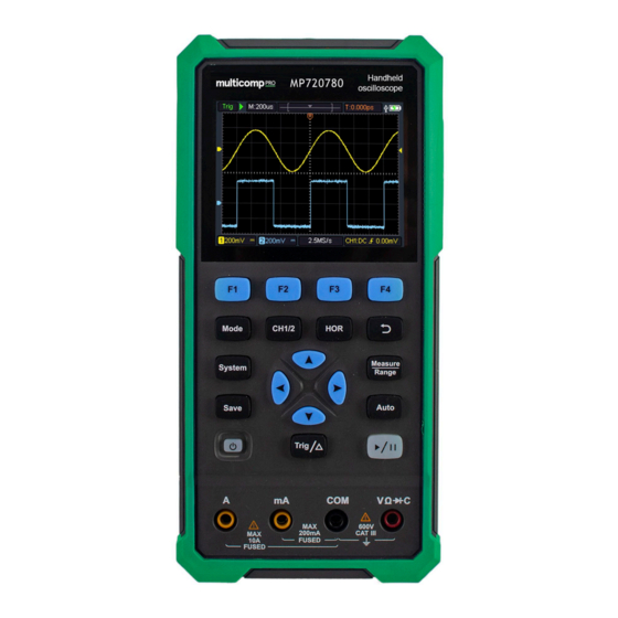
4. How to Use the Oscilloscope The Structure of the Oscilloscope Front Panel and Keys The front panel and keys of the oscilloscope are shown in Figure 4: Figure 4: Front Panel of the Oscilloscope Description: 1. CH1 and CH2 input connectors. 2. - Page 10 5. After pressing the HOR key, through the key , you can change the horizontal time base setting, and observe the change of the state information caused by it; it can also be found that the horizontal time base display corresponding to the status bar has changed correspondingly; the horizontal displacement of the signal in the waveform window can be adjusted by pressing 6.
-
Page 11: Side Panel
Side Panel Description: 1. Probe compensation: 3.3V/1kHz square wave signal output 2. Charging or USB communication interface 3. Bracket... -
Page 12: Introduction To The User Interface Of The Oscilloscope
Introduction to the User Interface of the Oscilloscope 1 2 3 Figure 5: Oscilloscope Interface Description: 1. The trigger status indicates the following information: Auto: Automatic mode. The waveform is being collected without triggering. Trig: A trigger has been detected and post trigger information is being collected. -
Page 13: Functional Check
10. Channel 2 waveform. 11. The icon indicates trigger-related information, including trigger channel, coupling mode, trigger type and trigger electrical level. For details, please refer to P19 Trigger System. 12. The current sampling rate. 13. The channel information reading indicates the voltage position of the corresponding channel. -
Page 14: Probe Compensation
the CH1 connector and insert it, then turn the probe to the right and tighten it. Connect the probe tip and ground clamp to the connector of the probe compensator. Please pay attention to the terminal polarity. The square terminal represents the signal output, and the round terminal represents the reference ground. -
Page 15: Probe Attenuation Coefficient Setting
2. Check the displayed waveform and adjust the probe until the compensation is correct. See Figure 0-2 and Figure 0-3. Overcompensation Correct compensation Under-compensation Figure 0-2: Display Waveform of Probe Compensation 3. Repeat the steps if necessary. Figure 0-3: Probe Adjustment Probe Attenuation Coefficient Setting The probe has a variety of attenuation coefficients, which will affect the vertical position factor of the oscilloscope. -
Page 16: Safe Use Of Probe
Note: The preset setting of the probe attenuation coefficient in the menu when the oscilloscope is delivered is 10X. Make sure that the attenuation switch setting value on the probe is the same as the probe attenuation coefficient option in the oscilloscope menu. -
Page 17: Vertical System
Warning: To prevent electric shock when using the probe, please keep your fingers behind the safety ring on the probe body. To prevent electric shock when using the probe, do not touch the metal part of the probe head when the probe is connected to a voltage source. -
Page 18: Horizontal System
Disconnect the input signal. Choose one of the values according to the probe attenuation factor to keep the vertical scale Probe 100X reading accurate. 1000X Limit the bandwidth to 20MHz to reduce display noise. Bandwidth Full bandwidth The bandwidth of the oscilloscope. Horizontal System Press the HOR key to enter the horizontal system setting menu. -
Page 19: Measuring System
Measuring System Automatic Measurement Press and the F1 key to realize automatic measurement. There are 7 types of measurement, and up to 6 types of measurement can be displayed at the bottom left of the screen. Auto range includes frequency, period, amplitude, maximum, minimum, peak-to-peak value, and average value. - Page 20 When the type is selected as CH1 or CH2, press the arrow keys to move the cursor line A; when the type is selected as Time, press the arrow keys to move the cursor line a. When the type is selected as CH1 or CH2, press the arrow keys to move the cursor line B;...
- Page 21 bottom right corner of the screen, e.g. . It indicates that the trigger type is rising edge, the trigger source is CH1, the trigger coupling is DC, and the trigger electrical level is -20.0mV. The description of the trigger system setting menu is as follows: Function Description Setting...
- Page 22 Settings Any setting can be saved inside the oscilloscope, and restore settings can also be called. The description of Setting menu is as follows: Function Description Setting Menu Target Set waveform name. Save the current parameter settings of the Save oscilloscope to the internal memory.
- Page 23 File The file can be saved as waveform or image. The waveform and image can be read by plugging and unplugging the USB data cable or selecting MSC in the USB option on the next page of system settings. The description of File menu is as follows: Function Description...
- Page 24 Elapsed 00h:00m Display how long it has been powered on. runtime System The description of the menu is as follows: Function Description Setting Menu Simplified Language Chinese Set the menu language. English 10 minutes Set the automatic shutdown time. Unlimited Shutdown 30 minutes means no shutdown.
-
Page 25: How To Use The Multimeter
the built-in memory. 2) HID [Human interface Device] is used to select the oscilloscope device as the host computer to control and communicate with the computer. Factory Settings To set the factory settings, press the System key. Press the menu selection key F4 to enter the next page. - Page 26 Multimeter interface: Multimeter Interface Description: 1. Measurement type indication: ------ DC voltage measurement ~ ACV ------ AC voltage measurement ------ DC current measurement ~ ACA ------ AC current measurement Resist ------ Resistance measurement Diode ------ Diode measurement Cont ------ On/Off measurement ------ Capacitance measurement 2.Range indication: Manual means manual range;...
- Page 27 6. “Hold” can keep the current reading on the display. 7. Measurement value and unit. 8. Display of switching resistance, buzzer, diode and capacitance measurement function. 9. The selected range V or mV in voltage measurement; the selected current range A or mA in current measurement. 10.
-
Page 28: How To Use The Waveform Generator
6. How to Use the Waveform Generator (MP720781, MP720783 and MP720857) The instrument can provide 4 basic waveforms, sine wave, square wave, ramp wave, pulse wave, and 8 arbitrary waveforms. Connect the output Press the Mode button to switch the instrument interface to the waveform generator function interface. -
Page 29: Set The Load
Set the load Press the System key to enter the system function menu. Press the F4 key to enter the next page of menu. Press the F3 key to switch High Z / *Ω ("*" represents a value, the default is 50Ω). -
Page 30: Output The Square Waveform
Set the Offset / Low Level Press the F3 or F4 key to switch to the Offset/Low Level parameter, and then use the direction keys to set the desired value in the parameter column. Press F2 to switch between Offset / Low Level. Output the square waveform Press the F1 key to enter the square waveform setting interface. -
Page 31: Output The Arbitrary Waveform
Set the Pulse Width / Duty Cycle of the pulse waveform Press the key to switch to the Pulse Width/Duty Cycle parameter, use the direction keys to set the desired value in the parameter column. Press F2 to switch between Pulse Width / Duty Cycle. Set the Rise Time/Fall Time Press the F3 or F4 key to switch to the Rise Time/Fall Time parameter, use the... -
Page 32: Communication With Pc
7. Communication with PC The oscilloscope supports communications with a PC through USB. You can use the Oscilloscope communication software to store, analyze, display the data and remote control. To learn about how to operate the software, you can push F1 in the software to open the help document. -
Page 33: Troubleshooting
8. Troubleshooting 1. The oscilloscope cannot be turned on. It may be that the battery is completely exhausted. At this time, even if the oscilloscope is powered by the power adapter, the oscilloscope cannot be turned on. You need to charge the battery first, and do not turn on the oscilloscope. - Page 34 RUN/STOP. Check whether the trigger mode of the trigger mode menu is normal or single, and the trigger electrical level is out of the waveform range. If so, center the trigger electrical level or set the trigger mode to automatic. In addition, you can press Auto to automatically complete the above settings.
-
Page 35: Technical Specifications
"automatic correction" program (see automatic correction in "System Settings" on P18). All specifications are guaranteed except those marked "typical". Oscilloscope Characteristics Description MP720780;MP720781 40 MHz Bandwidth MP720782;MP720783 70 MHz MP720856;MP720857 100 MHz Channel Sampling method Sampling, peak detection Real-time MP720780 sampling rate MP720781 125 MSa/s (Dual channel) - Page 36 ≥10 Hz (AC coupling, -3dB) MP720781;MP720780 ≤ 8 ns Rise time MP720783;MP720782 ≤ 5 ns (typical on BNC) MP720856;MP720857 ≤ 3.5 ns DC gain accuracy 3% Cursor ΔV, ΔT, ΔT&ΔV between Period, Frequency, Mean, PK-PK, Automatic Measuremen Max, Min, Amplitude...
-
Page 37: Multimeter
Characteristics Description Trigger electrical ±0.3 div level accuracy According to Record length and time Trigger displacement base Edge trigging Slope Rising edge, falling edge The output of the probe compensator: Characteristics Description Output voltage 3.3Vpp, High-Z (typical) Frequency Square wave 1 kHz (±1%) (typical) Multimeter Characteristics... - Page 38 Minimum Basic Range Accuracy function resolution 10.000A ±(2.5%+2dig) Overload protection: Ma function: self-healing fuse 400 mA/250 V; Ampere function: 10A/600 V, D5.2*20, fast-acting fuse 200.00mA 10μA ±(1%+5dig) 10.000A ±(2.8%+5dig) frequency range:40Hz-1000Hz AC current Overload protection: Ma function: self-healing fuse 400 mA/250 V; Ampere function: 10A/600 V, D5.2*20, fast-acting fuse 200.00Ω...
-
Page 39: Arbitrary Waveform Generator (Mp720781, Mp720783 & Mp720857)
Arbitrary Waveform Generator (MP720781, MP720783 & MP720857) Characteristics Description Sine 0.1Hz~25MHz Square 0.1Hz~5MHz Ramp 0.1Hz~1MHz Waveform Frequency Pulse 0.1Hz~5MHz 0.1Hz~5MHz Sampling 125MSa/s Amplitude(50Ω 0.01Vpp ~ 2.5Vpp DC offset(High Z) ±(2.5V – Amplitude Vpp/2) Frequency Resolution 0.01% Channel Waveform Depth 14 bit Vertical Resolution Output Impedance 50 Ω... -
Page 40: General Technical Specifications
General Technical Specifications Display: Characteristics Description Display type 3.5-inch color LCD display Display resolution 320 horizontal × 240 vertical pixels Display color 65536 colors Display Contrast Adjustable Power supply: Characteristics Description 100 - 240 VACRMS, 50/60 Hz, CAT Ⅱ Power supply DC INPUT: 5VDC, 2A Power <5 W... -
Page 41: Appendix
Appendix A: List of Accessories 1 power adapter 1 USB cable 1 passive probes 1 crocodile clip cable (MP720780/MP720782/MP720856) 2 crocodile clip cable (MP720781/MP720783/MP720857) 1 set of multimeter probes 1 user manual 1 probe correction adjustment knife... -
Page 42: Appendix B: Maintenance And Cleaning
Appendix B: Maintenance and Cleaning General maintenance Do not store or place the instrument in a place where the LCD screen will be exposed to direct sunlight for a long time. Caution: Do not let spray, liquid or solvent touch the instrument or probe to prevent damage to the instrument or probe. - Page 43 Charging and Replacement of Battery If you want to store the oscilloscope for a long time, it is recommended to fully charge the lithium battery before storing. Battery Charging The lithium battery may not be fully charged when delivered. To make the battery fully charged, it takes up to 4.5 hours (when the device is turned off) or it is subject to the charging indicator.
- Page 44 Note To avoid overheating of the battery during charging, the ambient temperature must not exceed the allowable value given in the technical specifications. Replacement of Lithium Battery Generally, the battery does not need to be replaced. However, when necessary, it can only be replaced by qualified personnel, and only lithium batteries of the same specification can be used.
Need help?
Do you have a question about the MP720856 and is the answer not in the manual?
Questions and answers