
Subscribe to Our Youtube Channel
Related Manuals for FAAC 275 H600


Summary of Contents for FAAC 275 H600
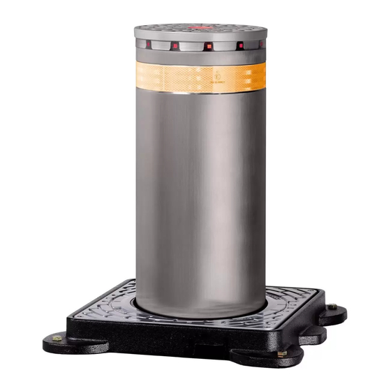
- Page 1 Automatic concealed bollards 275 H600 and 275 H800 Control station FAAC S.p.A. Via Benini, 1 40069 Zola Predosa Bologna (Italia) tel. +39 051 61724 www.faac.it...
- Page 2 Warnings for the installer Bollard electrical connection Technical specifications for control station Control station lay-out Dip-switches on control board Connection terminal boards for control boards FAAC S.p.A. Via Benini, 1 40069 Zola Predosa Bologna (Italia) tel. +39 051 61724 www.faac.it...
- Page 3 Additional information: These products underwent tests in a typical, uniform configuration (all products manufactured by FAAC S.p.A.). Bologna, 01 January 2005 The Managing Director A. Bassi FAAC S.p.A. Via Benini, 1 40069 Zola Predosa Bologna (Italia) tel. +39 051 61724 www.faac.it...
- Page 4 Make sure that a differential switch with a threshold of Anything not expressly specified in these instructions is not 0.03A is installed upstream of the system. permitted. FAAC S.p.A. Via Benini, 1 40069 Zola Predosa Bologna (Italia) tel. +39 051 61724 www.faac.it...
- Page 5 - For basic system with 5 FAAC CITIES - For system with 5 accessory FAAC CITIES 515 X 650 X 250 POLYESTER For basic system with 8 FAAC CITIES FAAC S.p.A. Via Benini, 1 40069 Zola Predosa Bologna (Italia) tel. +39 051 61724 www.faac.it...
- Page 6 - Traffic Lights Protection - Solenoid Valve Protection - Aux Protection PF6 - Aux Protection 24V START BUTTON ELECTRONIC CIRCUIT DIP-SWITCH FUNCTIONS Master equipment - Lay-out and components FAAC S.p.A. Via Benini, 1 40069 Zola Predosa Bologna (Italia) tel. +39 051 61724 www.faac.it...
- Page 7 - Pressure Sensor Input Opening Limit Switch Input - (Out) + 24V c.c. OK - AUX. Protection - Transformer Protection Slave equipment - Lay-out and components FAAC S.p.A. Via Benini, 1 40069 Zola Predosa Bologna (Italia) tel. +39 051 61724 www.faac.it...
- Page 8 Note: FAAC Cities connected to the Slave boards perform the same movements of the FAAC City connected to the Master board. If it is necessary to have different movements performed by various bollards, a Master board for every type of movement to be controlled must be installed.
- Page 9 Optional Emergency Button 230Vac Line Transformer 100 VA 230 V Id 30mA Prearrangement N.C. LOOP Optional Induttive Detector Master and Slave equipment - Power supply FAAC S.p.A. Via Benini, 1 40069 Zola Predosa Bologna (Italia) tel. +39 051 61724 www.faac.it...
- Page 10 Trasformer 100 VA 230 V 24 V 16 V Id 30mA Prearrangement N.C. LOOP Optional Induttive Detector Master and 2 Slave equipment - Power supply FAAC S.p.A. Via Benini, 1 40069 Zola Predosa Bologna (Italia) tel. +39 051 61724 www.faac.it...
- Page 11 4G1,5 SHIELDED CABLE CABLE 4G1 CABLE 5G0,5 5G0,5 SHIELDED CABLE CABLE 2x1 CABLE 2x1 CABLE 2x1 6G0,7 SHIELDED CABLE Control board terminals POWER CONNECTION - MODEL 275 FAAC S.p.A. Via Benini, 1 40069 Zola Predosa Bologna (Italia) tel. +39 051 61724 www.faac.it...
- Page 12 FUNCTIONS OF DIP-SWITCHES OF FAAC CITY MASTER EQUIPMENT Dip-switch No. 1 on the FAAC City Master board enables you to select the system's function logic (automatic or semi-automatic). Dip-switches 2, 3, 4, and 5 were fitted to facilitate diagnostic operations during repair/maintenance of the systems.
- Page 13 24/25 – 26/27 – 58/59 are in operation. ON Position = CONTROLS DISABLED: the bollard movement controls connected to terminals 24/25 – 26/27 – 58/59 are disabled. If the FAAC CITY bollard does not rise, you may temporarily disable the external control devices and use the push-button on the board (START) to carry out the test.
- Page 14 ON Position = REVERSING PRESSURE SWITCH DISABLED: the function described above is disabled. If the FAAC CITY bollard does not rise or, if during the rise stage, the bollard re-descends for no apparent reason, you may temporarily exclude this function to check if the pressure switch is to blame for the fault.
- Page 15 Terminals 49-50 = connection for emergency lowering push-button Terminals 51-52= 230V connection to electronic circuit Terminal 53 = not used Terminal 54 = earth connection Terminals 55-56-57-58-59 = connection for weekly/annual clock FAAC S.p.A. Via Benini, 1 40069 Zola Predosa Bologna (Italia) tel. +39 051 61724 www.faac.it...
- Page 16 Terminals 22-23= 230V connection to electronic circuit Terminal 24 = not used Terminal 25 = earth connection Terminals 26-27-28= passing connection to 3-2-1 with (protective fuse) FAAC S.p.A. Via Benini, 1 40069 Zola Predosa Bologna (Italia) tel. +39 051 61724 www.faac.it...
- Page 17 FAAC S.p.A. Via Benini, 1 40069 Zola Predosa Bologna (Italia) tel. +39 051 61724 www.faac.it...
- Page 18 Distributor’s Stamp: The descriptions and illustrations contained in the present manual are not binding. FAAC reserves the right, whilst leaving the main features of the equipments unaltered, to undertake any modifications it holds necessary for either technical or commercial reasons, at any time and without revising the present publication.
Need help?
Do you have a question about the 275 H600 and is the answer not in the manual?
Questions and answers