Table of Contents
Advertisement
Quick Links
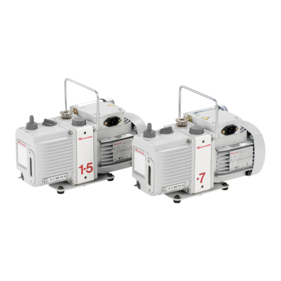
E2M0.7, E2M1 and E2M1.5
Rotary Vacuum Pumps
INSTRUCTION MANUAL
DESCRIPTION
3
-1
E2M0.7 (0.7 m
h
), 200-230 V, 50/60Hz
3
-1
E2M0.7 (0.7 m
h
), 100-120 V, 50/60 Hz
3
-1
E2M1.5 (1.5 m
h
), 200-230 V, 50/60 Hz
3
-1
E2M1.5 (1.5 m
h
), 200-230 V, 50/60 Hz (Interstage)
3
-1
E2M1.5 (1.5 m
h
), 100-120 V, 50/60 Hz
3
-1
E2M1.5 (1.5 m
h
), 100-120 V, 50/60 Hz (Interstage)
3
-1
E2M1 (1.0 ft
min
), 200-230 V, 50/60 Hz
3
-1
E2M1 (1.0 ft
min
), 100-120 V, 50/60 Hz
A37132880_F
edwardsvacuum.com
ITEM NUMBER
A37141919
A37141902
A37132919
A37104919
A37132902
A37104902
A37233919
A37233902
Original instructions
Advertisement
Table of Contents

Related Manuals for Edwards E2MO.7


Summary of Contents for Edwards E2MO.7
- Page 1 E2M0.7, E2M1 and E2M1.5 Rotary Vacuum Pumps INSTRUCTION MANUAL edwardsvacuum.com DESCRIPTION ITEM NUMBER A37141919 E2M0.7 (0.7 m ), 200-230 V, 50/60Hz A37141902 E2M0.7 (0.7 m ), 100-120 V, 50/60 Hz A37132919 E2M1.5 (1.5 m ), 200-230 V, 50/60 Hz A37104919 E2M1.5 (1.5 m ), 200-230 V, 50/60 Hz (Interstage) A37132902...
- Page 2 Vacuum pump and vacuum system safety P40040100 Trademark credit Edwards and the Edwards logo are trademarks of Edwards Limited, Innovation Drive, Burgess Hill, West Sussex RH15 9TW. Disclaimer The content of this manual may change from time to time without notice. We accept no liability for any errors that may appear in this manual nor do we make any expressed or implied warranties regarding the content.
- Page 3 CE Declaration of Conformity Edwards Ltd Innovation Drive Burgess Hill West Sussex RH15 9TW The following product AXXX - Pump type Variant Motor description E2M0.7 01 to 99 902 = 100-120V 50/60Hz Single Phase A371 = 912 = 200-230V 50/60Hz Single Phase E2M1.5...
- Page 4 Additional Legislation and Compliance Information EU RoHS Directive: Material Exemption Information This product is compliant with the following Annex III Exemptions 6(b) Lead as an alloying element in aluminium containing up to 0.4% by weight • 6(c) Copper alloy containing up to 4% lead by weight •...
-
Page 5: Table Of Contents
Contents 1. Safety and compliance........7 1.1 Definition of Warnings and Cautions. - Page 6 5.5 To pump condensable vapours........25 5.6 To decontaminate the oil.
- Page 7 10.2.11 Pump inlet or outlet NW25 adaptor......39 11. Service..........40 11.1 Return the equipment or components for service .
- Page 8 List of Figures Figure 1: General view of the pump..........11 Figure 2: Dimensions mm (inches).
-
Page 9: Safety And Compliance
A37132880_F - Safety and compliance 1. Safety and compliance 1.1 Definition of Warnings and Cautions NOTICE: This manual meets our obligation to provide you with information. For safe operation from the start, read these instructions carefully before you install or commission the equipment. - Page 10 A37132880_F - Safety and compliance Warning/Caution A safety instruction which must be followed. Warning - Dangerous voltage Identifies possible hazards from dangerous voltages. Warning - Hot surfaces Identifies a potential hazard from a hot surface. Warning - Use protective equipment Use appropriate protective equipment.
-
Page 11: Introduction
A37132880_F - Introduction 2. Introduction 2.1 Scope and definitions This manual provides installation, operation and maintenance instructions for our rotary vacuum pumps. The pump must be used as specified in this manual. Read this manual before installing and operating the pump. 2.2 ATEX directive implications This equipment is designed to meet the requirements of Group II Category 3 equipment in accordance with Directive 2014/34/EU of the European Parliament and the Council of... - Page 12 A37132880_F - Introduction Refer to Figure: General view of the pump on page 11 for item numbers in brackets in the following descriptions. The pumps are two-stage, direct drive, sliding vane pumps. The pump is oil-sealed and designed for reliable, long-term operation. The pump is a free-standing unit. The drive is provided through an Oldham coupling by a single-phase motor.
-
Page 13: Gas-Ballast
A37132880_F - Introduction Figure 1 General view of the pump 1. Fan cover 1. Fan cover 2. Motor terminal box 2. Motor terminal box 3. Handle (can be removed: see 3. Handle (can be removed: see Locate the Locate the 4. -
Page 14: Technical Data
A37132880_F - Technical data 3. Technical data 3.1 Operating and storage conditions Table 1 Operating and storage conditions Parameter Reference data Ambient temperature range (operation) 12 to 40 °C (53.6 to 104 °F) Ambient temperature range (storage) - 30 to 70 °C (-22 to 158 °F) Normal surface temperature of the pump- 50 to 70 °C (122 to 158 °F) body*... -
Page 15: Mechanical Data
A37132880_F - Technical data Maximum displacement E2M0.7 E2M1 E2M1.5 with full gas-ballast (partial pressure) 2 x 10 mbar 1.9 x 10 torr 2.5 x 10 mbar (2.5 Pa) (2.5 Pa) (2 x 10 Maximum water vapour inlet pressure 15 mbar 11.3 torr 15 mbar Maximum water vapour pumping rate... -
Page 16: Lubrication Data
A37132880_F - Technical data Figure 2 Dimensions mm (inches) 323 (12.71) 142 (5.59) 75 (2.95) 85 (3.34) 140 (5.51) 110 (4.33) 125 (4.92) 134 (5.27) 46.5 (1.83) 54 (2.12) 3.4 Lubrication data Note: A Material Safety Data Sheet for Ultragrade 15 is available on request. Table 4 Lubrication data Recommended oil* Ultragrade 15... -
Page 17: Electrical Cables
A37132880_F - Technical data Motor output rating - continuous 0.16 kW Motor electrical supply Single phase Table 5 Electrical data Pump Nominal supply (V) Frequency (Hz) Full load current (A) E2M0.7 100 - 115 100 - 120 200 - 230 0.85 200 - 240 E2M1 and E2M1.5... - Page 18 A37132880_F - Technical data Description Rating Coupler type Item number Cord set Cable style = SJT, 3 x 14 AWG, 300 V, assembly, USA/ 90 °C, VW-1 maximum length of Canada (200‑230 3.0 metres Plug type = NEMA, 6-15P plug Appliance coupler = IEC60320 style C14 Page 16...
-
Page 19: Installation
A37132880_F - Installation 4. Installation 4.1 Safety WARNING: Ensure that the installation technician is familiar with the safety procedures which relate to the pump oil and the products handled by the pumping system. WARNING: If a hydrocarbon oil is used in this pump, do not use the pump to process oxygen in concentrations greater than 25% in volume. -
Page 20: Unpack And Inspect
A37132880_F - Installation ▪ We recommend the use of a foreline vacuum isolation valve to allow the pump to warm up before pumping condensable vapours or if a vacuum needs to be maintained when the pump is not running. ▪ Avoid high levels of heat input to the pump from the process gases, otherwise the pump may overheat and seize, and cause the motor thermal overload device to open. -
Page 21: Fill The Pump With Oil
A37132880_F - Installation sight‑glass is visible and the oil filler‑plug, oil drain‑plug, mode selector and gas-ballast control are accessible. If the pump is part of a permanent installation the handle can be removed to make the pump more compact. To remove the handle, cut the handle into two and remove the free portions from the pump. -
Page 22: Check The Direction Of Rotation
A37132880_F - Installation 4.6.2 Check the direction of rotation CAUTION: Ensure that the pump-motor rotates in the correct direction. If it does not, the pump and the vacuum system can become pressurised. Refer to Figure: General view of the pump on page Watch the motor-cooling fan through the fan cover on the end of the motor. -
Page 23: Side Inlet-Port Connection
A37132880_F - Installation 4.7.2 Side inlet-port connection A side inlet-port is available, refer to Figure: General view of the pump on page 11. To use the side inlet-port, use the following procedure. Carefully remove the side panel from the pump: use a suitable flat blade screwdriver or similar tool for this purpose. -
Page 24: Operation
A37132880_F - Operation 5. Operation WARNING: Do not expose any part of the human body to vacuum. Failure to obey this warning could result in injury. 5.1 ATEX directive implications This equipment is designed to meet the requirements of Group II Category 3 equipment in accordance with Directive 2014/34/EU of the European Parliament and the Council of 26th February 2014 on the approximation of the laws of the Member States concerning equipment and protective systems intended for use in potentially explosive... -
Page 25: Gas Purges
A37132880_F - Operation 5.1.2 Gas purges WARNING: If using inert gas purges to dilute dangerous gases to a safe level, ensure that the pump is shut down if an inert gas supply fails. WARNING: Obey the instructions and take note of the precautions given below to ensure that pumped gases do not enter their flammable ranges. -
Page 26: Start-Up
A37132880_F - Operation 5.3 Start-up WARNING: Ensure that the system design does not allow the exhaust pipeline to be blocked If the oil is contaminated, or if the pump temperature is below 12 °C (53.6 °F), or if the electrical supply voltage is more than 10% below the lowest voltage specified for the pump, the pump may operate at a reduced speed for a few minutes. -
Page 27: To Pump Condensable Vapours
A37132880_F - Operation Close the gas-ballast control. Open the vacuum system isolation-valve and pump down to ultimate vacuum. 5.5 To pump condensable vapours Use gas-ballast (open the gas-ballast control) when there is a high proportion of condensable vapours in the process gases: Close the vacuum system isolation-valve. - Page 28 A37132880_F - Operation this, use a gas-ballast control valve (refer to Solenoid operated gas-ballast control valve on page 38). We recommend, as described in the procedure below, decontaminating the oil before shutting down the pump, this will prevent damage to the pump by the contaminates in the oil.
-
Page 29: Maintenance
A37132880_F - Maintenance 6. Maintenance 6.1 Safety information WARNING: Allow the pump to cool (so that it is at a safe temperature for skin contact) before starting maintenance work. Make sure the pump is switched off in case the thermal overload device restarts the pump. -
Page 30: Check The Oil Level
A37132880_F - Maintenance When carrying out maintenance on the pump, use our spares and maintenance kits, these contain all the components necessary to complete maintenance operations successfully. The item numbers of the spares and kits are given in Spares on page Examine the condition of any external accessory, filters or traps (if fitted) when carrying out maintenance on the pump. -
Page 31: Replace The Oil
A37132880_F - Maintenance 6.4 Replace the oil Refer to Figure: General view of the pump on page 11 for the items in brackets. Operate the pump for approximately ten minutes to warm the oil, then switch off the pump. (This lowers the viscosity of the oil and allows the oil to be drained from the pump more easily). -
Page 32: Clean Or Replace The Gas-Ballast O-Ring
A37132880_F - Maintenance Figure 3 Inlet-filter removal and replacement 1. Inlet adaptor 1. Inlet adaptor 2. Inlet-filter 2. Inlet-filter 3. O-ring 3. O-ring 6.6 Clean or replace the gas-ballast O-ring Note: The filter element is retained in its seating with adhesive, do not try to remove it. Refer to Figure: Gas-ballast O-ring removal and replacement on page Unscrew and remove the gas-ballast control. -
Page 33: Clean The Motor Fan-Cover And Enclosure
A37132880_F - Maintenance Figure 4 Gas-ballast O-ring removal and replacement 1. Gas-ballast control 1. Gas-ballast control 2. O-ring 2. O-ring 3. Filter element 3. Filter element 6.7 Clean the motor fan-cover and enclosure If the motor fan-cover and enclosure are not kept clean, the air flow over the motor can be restricted and the pump may overheat. -
Page 34: Fault Finding
A37132880_F - Fault finding 7. Fault finding A list of fault conditions and their possible causes is provided here to assist in basic fault‑finding. If unable to rectify a fault when using this guide, call your supplier or our nearest service centre for advice. 7.1 The pump has failed to start ▪... -
Page 35: The Vacuum Is Not Maintained After The Pump Is Switched Off
A37132880_F - Fault finding ▪ The electrical supply voltage is too high. ▪ The exhaust filter or exhaust line is blocked. ▪ The oil level is too low. ▪ The pump is filled with the wrong type of oil. ▪ The oil is contaminated. -
Page 36: Storage
A37132880_F - Storage 8. Storage CAUTION: Observe the storage temperature limits stated in Technical data on page 12. Storage below - 30 °C will permanently damage the pump seals. Note: If you will store a new pump in conditions of high humidity, remove the pump from its cardboard packaging box, dispose of the box (refer to Disposal on page 35). -
Page 37: Disposal
A37132880_F - Disposal 9. Disposal Dispose of the pump, the oil and any components removed from the pump safely in accordance with all local and national safety and environmental requirements. Particular care must be taken with components and waste oil which have been contaminated with dangerous process substances. -
Page 38: Spares And Accessories
A37132880_F - Spares and accessories 10. Spares and accessories Our products, spares and accessories are available from our companies in Belgium, Brazil, China, France, Germany, Israel, Italy, Japan, Korea, Singapore, United Kingdom, U.S.A and a world-wide network of distributors. The majority of these centres employ service engineers who have undergone comprehensive our training courses. -
Page 39: Inlet Catchpot
A37132880_F - Spares and accessories Figure 5 Accessories 1. Inlet catchpot 1. Inlet catchpot 2. Inlet dust filter 2. Inlet dust filter 3. Inlet desiccant trap 3. Inlet desiccant trap 4. Inlet chemical trap 4. Inlet chemical trap 5. Foreline trap 5. -
Page 40: Inlet Chemical Trap
A37132880_F - Spares and accessories 10.2.4 Inlet chemical trap The inlet chemical trap protects the pump against chemically active gases. Product Item number ITC20K Inlet chemical trap* A44410000 10.2.5 Solenoid operated gas-ballast control valve The valve provides remote or automatic on/off control of gas-ballast. The valve can be connected to shut-off ballast to prevent the return of air to the vacuum system when the pump is switched off. -
Page 41: Vibration Isolators
A37132880_F - Spares and accessories 10.2.10 Vibration isolators The vibration isolators reduce transmission vibration and noise when the pump is floor or frame mounted and to help to reduce strain when the mounting area is uneven. Product Item number Vibration isolators (pack of four) A24801407 10.2.11 Pump inlet or outlet NW25 adaptor This is a 3/8 inch BSP to NW25 adaptor, supplied with connection hardware. - Page 42 A37132880_F - Service 11. Service Our products are supported by a world‑wide network of our service centres. Each service centre offers a wide range of options including equipment decontamination, service exchange, repair, rebuild and testing to factory specifications. Equipment which has been serviced, repaired or rebuilt is returned with a full warranty.
- Page 43 A37132880_F - Service Page 41...
- Page 44 edwardsvacuum.com...
Need help?
Do you have a question about the E2MO.7 and is the answer not in the manual?
Questions and answers