Advertisement
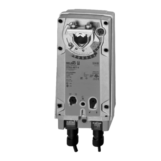
EFB and EFX Series Spring Return Direct Coupled Actuator
Minimum 270 in-lb Torque
●
For damper areas up to 66 sq-ft* (For lower torque, see AFB, AF, NFB, LF, or TF series)
A A pplications
New standard clamp fits standard 1/2" shafts to 1.05" jackshafts.
A A ll Actuators
have BDCM
EFB, EFX Series -
At A Glance
Torque:
270 in-lb
Power supply:
24 VAC/DC
120 VAC
230 VAC
Control signal:
On/Off
2 to 10 VDC
Multi-function**
Feedback signal:
2 to 10 VDC
VDC variable**
Running time motor: 75 seconds
95 seconds
Adj. 60 to 150 seconds***
spring: <20 seconds
Brushless DC Motor
External direction of rotation switch
Manual override
†
Appliance rated cable, 18 GA
A A (default)
Plenum rated cable, 18 GA (optional)
Built-in auxiliary switch, Two SPDT
NEMA 4 rated housing
Installation instructions......(p. 37-43)
*Based on 4 in-lb/ft
damper torque loading. Parallel blade. No edge seals. **Default 2 to 10 VDC. ***Default 150 seconds.
2
800-543-9038 USA
19
Mount directly to 1.05" jackshafts. (new ZG-120 bracket shown)
●
●
●
●
●
●
●
●
●
●
●
●
●
●
●
●
●
●
●
●
●
●
●
●
●
●
●
●
●
●
●
●
●
●
●
General wiring......(p. 45)
Start-up and checkout......(p. 46)
866-805-7089 CANADA
Linkage solutions are available when direct coupling is not possible.
●
●
●
●
●
●
●
●
●
●
●
●
●
●
●
●
●
●
●
●
●
●
●
●
●
●
●
●
●
●
●
●
●
●
●
●
●
●
●
●
●
●
●
●
●
●
●
●
●
●
203-791-8396 LATIN AMERICA / CARIBBEAN
●
●
●
●
●
●
●
●
●
●
●
●
●
●
●
●
●
●
●
●
●
●
●
●
●
●
●
●
●
●
●
●
●
●
●
●
●
●
●
●
●
●
●
●
Electrical operations......(p. 44)
●
●
●
●
●
●
●
●
●
●
●
Advertisement
Table of Contents

Related Manuals for Belimo EFB Series


Summary of Contents for Belimo EFB Series
- Page 1 EFB and EFX Series Spring Return Direct Coupled Actuator Minimum 270 in-lb Torque ● For damper areas up to 66 sq-ft* (For lower torque, see AFB, AF, NFB, LF, or TF series) A A pplications New standard clamp fits standard 1/2” shafts to 1.05” jackshafts. Mount directly to 1.05”...
- Page 2 ● Automatically compensates for damper seal wear, ensuring tight close-off. ● Added Flexibility to Select Clamp, Electrical Connection, and Running Time to fit your Specific Application with Belimo’s Flexible Line of Actuators (EFX). The Belimo Difference Customer Commitment. ● Extensive product range. Application assistance.
-
Page 3: Operation
EFB24, EFB24-S, EFX24, EFX24-S On/Off, Spring Return, 24 V Torque min. 270 in-lb, for control of air dampers Application For on/off, fail-safe control of dampers in HVAC systems. Actuator sizing should be done in accordance with the damper manufacturer’s specifications. Control is On/Off from an auxiliary contact, or a manual switch. - Page 4 Actuators may also be powered by 24 VDC. For actuator wiring information and diagrams, refer to Belimo Wiring Guide. For end position indication, interlock control, fan startup, etc., EFB24-S and EFX24-S incorporates two built-in auxiliary switches: 2 x SPDT, 3A (0.5A) Typical Specification @250 VAC, UL Approved, one switch is fi...
- Page 5 EFB24 N4, EFB24-S N4, EFX24-S N4(H) NEMA 4, On/Off, Spring Return, 24 V Torque min. 270 in-lb, for control of air dampers Application For On/Off, fail-safe control of dampers in HVAC systems. Actuator sizing should be done in accordance with the damper manufacturer’s specifications. Control is On/Off from an auxiliary contact, or a manual switch.
- Page 6 Power consumption and input impedance must be observed. For actuator wiring information and diagrams, refer to Belimo Wiring Guide. Actuators may also be powered by 24 VDC. For end position indication, interlock control, fan startup, etc., EFB24-S N4...
- Page 7 EFB120, EFB120-S, EFX120, EFX120-S On/Off, Spring Return, 100 to 240 VAC Torque min. 270 in-lb, for control of air dampers Application For On/Off, fail-safe control of dampers in HVAC systems. Actuator sizing should be done in accordance with the damper manufacturer’s specifications. Control is On/Off from an auxiliary contact, or a manual switch.
- Page 8 Power consumption and input impedance must be observed. listed on this page. No ground connection is required. For actuator wiring information and diagrams, refer to Belimo Wiring Guide. For end position indication, interlock control, fan startup, etc., EFB120-S and EFX120-S incorporates two built-in auxiliary switches: 2 x Typical Specification SPDT, 3A (0.5A) @250 VAC, UL Approved, one switch is fi...
- Page 9 EFB120-S N4, EFX120-S N4(H) NEMA 4, On/Off, Spring Return, 100 to 240 VAC Torque min. 270 in-lb, for control of air dampers Application For on/off, fail-safe control of dampers in HVAC systems. Actuator sizing should be done in accordance with the damper manufacturer’s specifications. Control is On/Off from an auxiliary contact, or a manual switch.
- Page 10 ZG-EFB Crank arm adaptor kit Note: When using EFB120-S N4, EFX120-S N4(H) actuators, only use accessories listed on this page. For actuator wiring information and diagrams, refer to Belimo Wiring Guide. EFB120-S N4 Typical Specification EFX120-S N4 On/Off spring return damper actuators shall be direct coupled type which require...
- Page 11 EFB24-SR, EFB24-SR-S, EFX24-SR, EFX24-SR-S Proportional, Spring Return, 24 V, for 2 to 10 VDC or 4 to 20 mA Control Signal Torque min. 270 in-lb, for control of air dampers Application For proportional modulation of dampers in HVAC systems. Actuator sizing should be done in accordance with the damper manufacturer’s specifications.
- Page 12 NOTE: When using EFB24-SR, EFB24-SR-S, EFX24-SR and EFX24-SR-S actuators, only use 2 to 10 VDC 5 U Output accessories listed on this page. 2 to 10V For actuator wiring information and diagrams, refer to Belimo Wiring Guide. EFB24-SR, EFB24-SR-S EFX24-SR, EFX24-SR-S Typical Specification 2 to 10 VDC control Spring return control damper actuators shall be direct coupled type which require no crank arm and linkage and be capable of direct mounting to a jackshaft up to a 1.05”...
- Page 13 EFB24-SR N4, EFB24-SR-S N4, EFX24-SR-S N4(H) NEMA 4, Proportional, Spring Return, 24 V, for 2 to 10 VDC or 4 to 20 mA Control Signal Torque min. 270 in-lb, for control of air dampers Application For proportional modulation of dampers in HVAC systems. Actuator sizing should be done in accordance with the damper manufacturer’s specifications.
- Page 14 NOTE: When using EFB24-SR N4, EFB24-SR-S N4, and EFX24-SR-S N4(H) actuators, only use (–) Control Signal accessories listed on this page. 2 to 10 VDC For actuator wiring information and diagrams, refer to Belimo Wiring Guide. 5 U Output 2 to 10V EFB24-SR N4, Typical Specification...
- Page 15 9.5 W These parameters can be changed by three means: consumption holding 4.5 W • Pre-set or custom configurations from Belimo Transformer sizing 16 VA • Configurations set by the customer using the MFT PC tool (version 3.4 or higher) Electrical connection software application.
- Page 16 ZG-EFB Crank arm adaptor kit NOTE: When using EFB24-MFT, EFB24-MFT-S, EFX24-MFT and EFX24-MFT-S actuators, only use accessories listed on this page. For actuator wiring information and diagrams, refer to Belimo Wiring Guide. 10° to 85° EFX24-MFT-S Typical Specification EFX24-MFT-S N4...
- Page 17 24 VAC, +/- 20%, 50/60 Hz These parameters can be changed by three means: 24 VDC, +20% / -10% • Pre-set or custom configurations from Belimo Power running 9.5 W / heater 21 W • Configurations set by the customer using the MFT PC tool (version 3.4 or higher) software application.
- Page 18 Crank arm adaptor kit NOTE: When using EFB24-MFT-S N4, and EFX24-MFT-S N4(H) actuators, only use accessories listed on this page. For actuator wiring information and diagrams, refer to Belimo Wiring Guide. 85° Typical Specification Spring return control damper actuators shall be direct coupled type which require no crank arm and linkage and be capable of direct mounting to a jackshaft up to a 1.05”...
-
Page 19: Installation Instructions
Installation Instructions Quick-Mount Visual Instructions for Mechanical Installation Quick-Mount Visual Instructions 1. Rotate the damper to its fail-safe position. If the shaft rotates counterclockwise, mount the “CCW” side of the actuator out. If it rotates clockwise, mount the actuator with the “CW” side out. 2. - Page 20 Installation Instructions K9-2 Universal Clamp 1/2” ... 3/4” 1/2” ... 11/16” 3/4” ... 1.05” 1/2” ... 11/16” < 1.05“ < 3/4“ < 1/2“ 11 ft-lb 1 / 2 ” s t a i n l e s s s t e e 18.5 ft-lb 800-543-9038 USA 866-805-7089 CANADA...
-
Page 21: Mechanical Installation
), this is a CW installation. In a CCW installation, the actuator side installing contractor to allow space for mounting and service of the Belimo actuator on the shaft. The damper shaft must extend at least 4-3/4” from the duct. If the shaft marked “CCW”... - Page 22 Installation Instructions Mechanical Installation position the clamp so that the pointer section of the tab is pointing to 0° (see MOUNTING: If the actuators are mounted on the opposed ends of the shaft, the Figure C) and the spline pattern of the clamp mates with spline of the actuator. actuator direction must be selected carefully.
- Page 23 Installation Instructions Mechanical Installation Rotation Limitation The angle of rotation limiter, which is built into the actuator, is used in conjunction with the tab on the universal clamp or IND-EFB position indicator. In order to function properly, the clamp or indicator must be mounted correctly. See Figure A.
- Page 24 Installation Instructions Mechanical Installation Manual Override Auxiliary Switches The EFB, EFX series actuators can be manually positioned to ease installation or for The EFB, EFX series actuators may be ordered with two built-in SPDT auxiliary emergency positioning. switches used for safety interfacing or signaling, for example, for fan start-up. The switch position near the fail-safe position is fixed at 10°.
- Page 25 Installation Instructions Non-Direct Mounting Methods KH EFB C KH-EFB Crank Arm Including Retaining Ring The KH-EFB crank arm is used in non-direct coupled mounting applications. The KH- EFB may also be used to simultaneously direct couple to a damper shaft and provide an additional crank arm connection to a second damper.
-
Page 26: Electrical Operation
The electromagnetic to control signal instability. poles are switched by a special ASIC circuit developed by Belimo. Unlike the conventional DC motor, there are no brushes to wear or commutators to foul. -
Page 27: General Wiring Instructions
MAXIMUM WIRE LENGTH FOR 16VA before making any connections. Follow all instructions in this literature. If you Wire Size Max. Feet. Wire Size Max. Feet have any questions, contact the controller manufacturer and/or Belimo. 12 Ga 550 Ft. 18 Ga 145 Ft. 14 Ga 360 Ft. -
Page 28: Startup And Checkout
• If multiple transformers are used with one control signal, make sure all No. 1 wires are tied together and tied to control signal negative (-). • Controllers and actuators must have separate 24 VAC/VDC power sources. NOTE 2 If failure occurs within 5 years from original purchase date, notify Belimo and give details of the application. 800-543-9038 USA 866-805-7089 CANADA...
Need help?
Do you have a question about the EFB Series and is the answer not in the manual?
Questions and answers