Advertisement
Quick Links
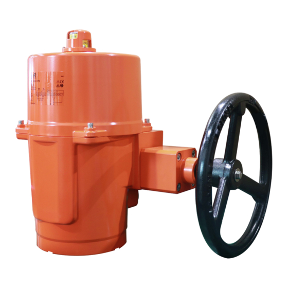
SY..-3-T-TS actuators for 3-point control or open/close control
Wiring Diagram
"L" (Live wire) connects to terminal #3 for OPEN.
"L" connects to terminal #4 for CLOSE.
Connect "L" to terminal #7 to activate the internal heater. (No
need to connect internal heating for indoor applications with
constant temperature conditions.)
Note:
"L" shall not connect to terminal #3 and #4
1)
simultaneously
!
Relays are needed in parallel connection of
2)
several actuators!
30% duty cycle
3)
If it is necessary to change the following settings,
!
only authorized and trained personnel are allowed
to do so.
Install to butterfly valve
Manual operate the actuator to the
1)
similar open position of the valve,
which can be judged by the valve
disc.
Fit coupling on the top stem of the
2)
valve.
Mount the actuator onto the
3)
coupling,
manual
operate
actuator to align the holes of valve
top flange and actuator bottom;
then tighten the bolts by wrench in
diagonal sequence.
Remove the actuator cover, wire
4)
according to the wiring diagram.
Power on to test run the actuator,
5)
check its travel angle and feedback
position,
make
adjustment
necessary.
Put the cover on and tighten the
6)
bolts
Limit switches LS.. with travel cams TC..
Note: TC1 and TC2 switches are carefully calibrated at factory and
adjustment is normally not needed. Adjustment on these limit
switches must be carried out by trained personnel and wrong
adjustment could damage the system.
The TC.. cams rotate with the shaft, and trigger the LS.. limit
switches. Clockwise movement of the shaft closes the actuator,
counterclockwise movement opens the actuator.
There are 4 cams included, marked with two colors: blue for open,
silver for close; each cam can be set independently.
Auxiliary switch for closed (factory setting 3⁰)
Auxiliary switch for open (factory setting 87⁰)
Closed switch (factory setting 0⁰)
Open switch (factory setting 90⁰)
the
if
How to adjust the travel
1.
cam
1.1. Loosen the cam to be
adjusted
with
2.5mm allen key;
1.2. By turning the key,
rotate and adjust the
cam as shown in the
diagram on the right;
1.3. Check if the valve can open and close properly
1.4. Tighten the cam after successful adjustment
Closed position (0%) setting
2.
2.1. Connect power to terminal #1 and #4.
2.2. Power on. The actuator will drive CW to fully closed
position.
2.3. Adjust travel cam TC2 in the closed position.
2.4. Check whether LS2 switch trips prior to manual
operation stop. (When motor stops at fully closed
position, it should be possible to further operate the
handwheel CW ½...¾ turn. Otherwise the stop screw for
manual closed limit need to be adjusted.)
Adjust similarly for TC1 in open position by connecting power
3.
to terminal #1 and #3.
Limiting of manual rotation with top screws
Note: Top screws for manual OPEN and CLOSE limit are carefully
calibrated at factory and adjustment is normally not needed.
Adjustment on these screws must be carried out by trained
personnel and wrong adjustment could damage the system.
SY quarter-turn actuator is provided with a limiting of manual
rotation device to avoid over-travel with the handwheel going
beyond the ¼-turn rotation.
The actuator is supplied and tested for 90⁰ electrical operation, and
-2⁰...92⁰ limiting of manual rotation.
The limiting of manual rotation is realized by the stop screws 1 and
2 (max. ±2⁰ which corresponding to 1 turn of the stop screw).
The top screws must be secured
with the lock nut after any
adjustment. (by both an allen key
and a wrench)
The 90⁰ travel must always be
limited
by
the
travel
limit
switches so they must be set to
trip just BEFORE contacting the
Stop screws.
To achieve this, loose stop screws by 2½ turns. After travel limit
switch setting is completed, operate the actuator electrically to
closed position. (See paragraph Limit switches LS.. with travel
cams TC..) Now rotate the stop screw 2 to closed position, re-
loosen 1 turn, and secure by lock nut. Proceed in the same way for
stop screw 1 in open position. The limiting of manual rotation
device is only a design feature to prevent over-travel when the
actuator is being operated manually, it is not a safety function to
prevent over-travel in the event of travel limit switch failure.
Overload protection
This actuator is equipped with a torque switch that breaks the
power when an overload condition appears. An alarm switch will
be triggered when the torque limit switch activates.
TS3: When the torque value is overloaded, terminal #8 will loop to
terminal #9 when actuator turns counterclockwise.
TS4: When the torque value is overloaded, terminal #11 will loop to
terminal #12 when actuator turns clockwise.
a
1- Stop screw for manual OPEN limit
2- Stop screw for manual CLOSED limit
3- Handwheel connection
Advertisement

Subscribe to Our Youtube Channel
Related Manuals for Belimo SY-3-T-TS Series


Summary of Contents for Belimo SY-3-T-TS Series
- Page 1 SY..-3-T-TS actuators for 3-point control or open/close control Wiring Diagram How to adjust the travel 1.1. Loosen the cam to be adjusted with 2.5mm allen key; 1.2. By turning the key, rotate and adjust the "L" (Live wire) connects to terminal #3 for OPEN. cam as shown in the "L"...
- Page 2 SY..-3-T-TS 执行器用于三态控制或开/关控制 接线说明 1.2. 用内六角扳手按图所示方法调 整行程凸轮位置,并预拧 紧螺丝。 1.3. 检查阀门是否能正常开或关。 1.4. 成功调整完毕后必须锁定行程凸轮。 关闭位置(0%)设定 2.1. 端子 #1, #4 连接电源; 2.2. 通电,执行器会顺时针转动至全关位置。 L(火线)与端子#3 连接为打开 2.3. 调节行程凸轮 TC2 至全关位置。 L 与端子#4 连接为关闭 2.4. 检查电子限位行程是否在机械限位范围之内。(即马达 L 与端子#7 连接,激活内置电加热(恒温的室内应用中,无需连 于 全 关 位 置 停 止 后 , 逆 时 针 方 向 操 作 手 轮 能 旋 转 接内置电加热。)...
Need help?
Do you have a question about the SY-3-T-TS Series and is the answer not in the manual?
Questions and answers