Table of Contents
Advertisement
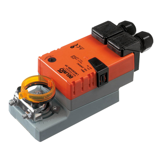
LM Series Direct Coupled Actuator
Small Yet Powerful
Minimum 35 in-lb torque in a compact package.
For damper areas up to 8 sq-ft*.
Areas of Application
VAV Units and Small Zone Dampers
©
Actuators
in bold have
BDCM
LM Series – at a glance
Torque:
35 in-lb
Power supply : 24 VAC/DC
Brushless DC motor:
Control signal: on-off
floating point
proportional 2 to 10 VDC
Multi-function**
Feedback signal: 2 to 10 VDC
VDC variable**
10kΩ feedback potentiometer
5kΩ feedback potentiometer
Run time:
95 sec
80 to 110 sec for 0 to 35 in-lb
25 to 35 sec for 0 to 18 in-lb
Adj. 75 to 300 sec.***
Left/Right rotation switch
Angle of rotation limiting (mechanical)
Angle of rotation limiting (electronic)
Plenum rated cable, 18 GA
Screw terminal strip
Manual Override push-button
Built-in auxiliary switch
Installation Instructions ......(p. 168–170)
Start-up and checkout ......(p. 171)
2
*Based on 4 in-lb/ft
damper torque loading. Parallel blade. No edge seals. **Default 2 to 10 VDC ***Default 150 seconds
Halomo Brushless DC Motor Technology
156
Rack and pinion type actuator
replaced by direct coupled LM.
Replacement LM24 compatible
with existing control system.
General wiring ..............(p. 169)
®
Quiet Plus
VAV
terminal unit by
Warren Technology
Replacement Belimo
actuator (LM type)
direct couples to VAV
Existing pneumatic
By-Pass damper shaft.
actuator requires linkage.
®
Advertisement
Table of Contents

Related Manuals for Belimo LM Series


Summary of Contents for Belimo LM Series
- Page 1 By-Pass damper shaft. actuator requires linkage. with existing control system. © Actuators in bold have BDCM LM Series – at a glance Torque: 35 in-lb Power supply : 24 VAC/DC Brushless DC motor: Control signal: on-off floating point proportional 2 to 10 VDC...
- Page 2 ® LM Series Direct Coupled Actuator A CLOSER LOOK… LISTED 94D5 TEMP. IND & REG. EQUIP Brushless DC Motor for added accuracy and controllability. Cut labor costs with simple direct coupling. Check damper position from a distance with clear position indication.
- Page 3 LM24-3 (-T) US / LM24-3 (-5P0) (-T) US ® On-off/ floating point control, non-spring return, direct coupled, 24 V Torque min. 35 in-lb, for control of damper surfaces up to 8 sq ft. LM24-3 US LISTED LM24-3-T US 94D5 TEMP. IND & ...
- Page 4 5 kΩ feedback potentiome- ter (LM24-3-5P0-T US) for use in modulating (floating point) To have better control of job site inventory and reduce the applications. Actuators shall be as manufactured by Belimo. environmental impact of unnecessary packing material.
- Page 5 LM24-SR (-T) US ® Proportional control, non-spring return, direct coupled, 24 V, for 2 to 10 VDC and 4 to 20 mA control signal Torque min. 35 in-lb, for control of damper surfaces up to 8 sq ft. LM24-SR US LISTED LM24-SR-T US 94D5...
- Page 6 10VDC output relative to position regardless of the amount of damper rotation. A 2 to 10 VDC feedback signal shall be Bulk packaging LM24-SR US and LM24-SR-T US provided for position indication or master-slave applications. Actuators shall be as manufactured by Belimo. Bulk Pack No. Actuator Type Quantity/Pack An electronic angle of rotation adjustment shall be provided to LM24-SR .1 US...
- Page 7 ® LM24-S US, LM24-10P US On-off control, non-spring return, direct coupled, 24 V Torque min. 35 in-lb, for control of damper surfaces up to 8 sq ft. LM24-S US LISTED LM24-10P US 94D5 TEMP. IND & REG. EQUIP Application For on-off control of dampers in HVAC systems.
- Page 8 If required, actuators shall be provided with a built-in 10 kΩ feed- a 10 kΩ feedback potentiometer. back potentiometer (LM24-10P US) for use in modulating (floating Value based on resistance between (P1) and (P2). point) applications. Actuators shall be as manufactured by Belimo. indicates direction of rotation of actuator.
- Page 9 LMC24 (-SR) (-T) US ® Non-spring return, direct coupled, 24 V, 25 to 35 sec. running time Torque min. 18 in-lb, for control of damper surfaces up to 4.5 sq ft. LMC24 US (on/off) LISTED LMC24-SR US (proportional) 94D5 LMC24-SR-T US (proportional) TEMP.
- Page 10 Actuators may also be powered by 24 VDC and feedback control range. Actuators shall be as manufac- Actuators are provided with color coded wires. Wire tured by Belimo. numbers are provided for reference. Connect actuator common (Wire 1) to Negative (–) leg of control circuits only.
- Page 11 These parameters can be changed by three means: TEMP. IND & REG. EQUIP • Pre-set configurations from Belimo • Custom configurations from Belimo • Configurations set by the customer using the MFT-Handy ® or the MFT-Actuate™ PC software application.
- Page 12 LM24-MFT US ® ® Proportional damper actuator, non-spring return, Multi-Function Technology Standard Wiring Standard Wiring 24 VAC Transformer 24 VAC Transformer Common Line Common Line Volts Volts + Hot + Hot 500Ω Ω 1/4 watt Control Signal (–) (–) Control Signal 2 to 10 VDC (3) Y 4 to 20 mA...
- Page 13 Preliminary steps Belimo actuators should be mounted indoors in dry, relatively clean environment free from corrosive fumes. If the actuator is to be mounted outdoors, a protective enclosure must be used to shield the actuator. (See Belimo Mechanical Accessories section) For new construction work, order dampers with extended shafts.
- Page 14 Max. Feet Transformer(s) 16 Ga 1225 Ft. 20 Ga 400 Ft The LM Series actuators require a 24 VAC class 2 transformer 18 Ga 725 Ft. 22 Ga 200 Ft and draw a maximum of 4 VA. The actuator enclosure cannot Fig.
- Page 15 Direction of rotation switch. Position indicates start point. reversed and the actuator will reverse its direction. This allows Mechanical Angle of Rotation Limiting (LM Series, On-Off/Floating and LM24-SR-T US) The adjustable stops are needed when there is no damper stop or if you want the damper to halt rotating before it reaches its stops.
- Page 16 • If multiple transformers are used with one control signal, make sure all No. 1 wires are tied together and tied to control signal negative (-). • Controllers and actuators must have separate 24 VAC/VDC power sources. Note 2 If failure occurs within 5 years from original installation date, notify Belimo and give details of the application.
Need help?
Do you have a question about the LM Series and is the answer not in the manual?
Questions and answers