Advertisement
Quick Links
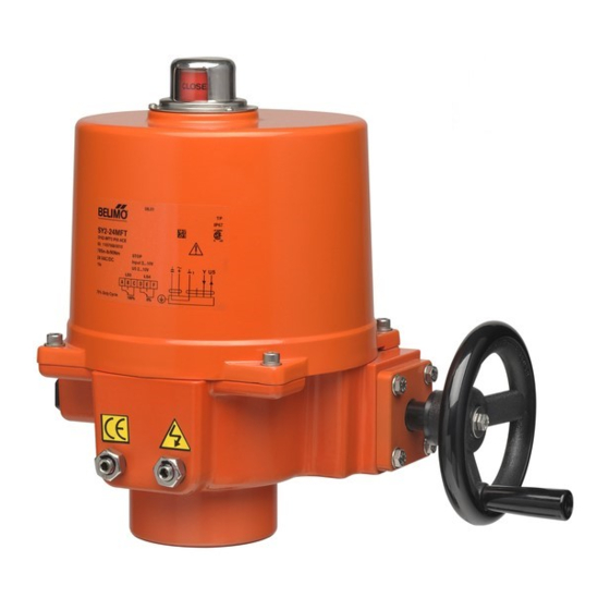
SY..-3-T actuators for 3-point control or Open/close control
Wiring diagram
Connect via safety
!
AC 24 V
isolating transformer
N
L1 AC220~230 V
1 3 4 5 6 7
H
Note: 1) "L1" cannot connects to terminal #3 and #4
simultanenously.
!
2) Relays are needed in parallel connection of several
actuators!
3) 30% duty cycle
If it's necessary to change the following settings, only
!
authorized and trained persons are allowed to do that.
Install to butterfly valve
1).
Manual operate the actuator
to the similar open position
of the valve, which can be
judged by the valve disc or
the red line on the valve top
stem.
2).
Fit coupling on the top stem
of the valve.
3).
Mount the actuator onto the
coupling, manual operate
the actuator to align the holes
of valve top flange and actu-
ator bottom; then tighten the
bolts by wrench in diagonal
sequence.
4).
Uncover the actuator, wire
according to the wiring diag-
ram.
5).
Power on to test run the
actuator, check its stroke
and feedback position, do
some adjustment if necessary.
6).
Put the cover on and tighen
the bolts for it.
Limit switches LS.. with travel cams TC..
The TC.. cams operating the LS.. limit switches rotate with the shaft.
Clockwise movement of the shaft closes the actuator, counterclockwise
opens the actuator.
There are 4 cams included , marked with two colors : blue for open,
silver for close; each cam can be set independently.
shaft
TC4
LS4
LS3
TC3
LS2
LS1
TC2
TC1
eg. SY1..~SY12..
Auxilary Switches
(SPDT Relays)
A
B
C
E
F
SY1
S1 100%
A
B
C
D
E
F
SY2...12
S1 100%
S2 0%
The line indicates
the position of the
valve's disc
± 1°
Auxiliary switch for closed
(factory setting 3°)
Auxiliary switch for open
(factory setting 87°)
Closed switch
(factory setting 0°)
Open switch
(factory setting 90°)
1. How to adjust the travel cam
Loosen the cam to be adjusted
1.1
with a 2.5 mm allen key;
By turning the key rotate and
1.2
adjust the cam as shown in
the right diagram;
Commission;
1.3
Tighten the cam after succes-
1.4
sful adjustment.
2. Closed position (0%) setting
Wiring on terminal #1, #4;
2.1
Power on. The actuator will drive CW to fully closed position.
2.2
Adjust travel cam TC2 in the closed position.
2.3
Check whether LS2 switch trips prior to manual operation stop.
2.4
(So when motor stops at fully closed position, it should be
possible to further operate the handwheel CW 1/2...3/4 turn.
Otherwise the stop screw for close need to be adjusted.)
Proceed in the similar way for TC1 in open position.
Limiting of manual rotation with stop screws
SY quarter-turn actuator is provided with a limiting of manual rotation
device to avoid over-travel with the handwheel going beyond the 1/4-turn
rotation.
The actuator is supplied and tested for
...92° limiting of manual rotation.
The limiting of manual rotation is realized by the stop screws 1 and 2
( max. ± 2° which corresponding to 1 turn of the stop screw).
The stop screws must be sec-
ured with the lock nut after any
adjustment. (by both a allen key
and a wrench)
The 90° travel must always be
limited by the travel limit sw-
itches so they must be set to
trip just BEFORE stop screw's
contact.
To achieve this, loose
stop screws by 2 1/2 turns. Then,
after travel limit switch setting is
terminated, (see paragraph
Limit switches LS.. with travel cams
rically to closed position. Now rotate the stop screw 2 to closed position,
re-loose 1 turn, and secure by lock nut. Proceed in the same way for stop
screw 1 in open position.
It is emphasized that the limiting of manual rotation device is only a design
feature to prevent over-travel when the actuator is being operated manually,
not a safety function to prevent over-travel in the event of travel limit
switch failure.
Open
Current position
Required position
Close
90°
electrical operation, and -2°
3
1
2
1- Stop screw for manual OPEN limit
2- Stop screw for manual CLOSED limit
3- Handwheel connection
(Note: SY1 without the device)
TC..), operate the actuator elect-
Advertisement

Subscribe to Our Youtube Channel
Related Manuals for Belimo SY 3-T Series


Summary of Contents for Belimo SY 3-T Series
- Page 1 SY..-3-T actuators for 3-point control or Open/close control Wiring diagram 1. How to adjust the travel cam Auxilary Switches Connect via safety (SPDT Relays) AC 24 V isolating transformer Loosen the cam to be adjusted Open L1 AC220~230 V with a 2.5 mm allen key; By turning the key rotate and S1 100% adjust the cam as shown in...
- Page 2 SY..-3-T 执行器 接线说明 1. 如何调整行程凸轮 通过安全隔离 辅助开关 AC 24 V 的变压器连接 将2.5 mm内六角扳手插入所要设定的 L1 AC 220~230 V 开 行程凸轮的螺孔内,松动螺栓。 用内六角扳手按右图所示方法调 S1 100% 整行程凸轮位置,并预拧紧螺丝。 1 3 4 5 6 7 当前位置 通电检查电子行程开关LS的动作 正确位置 SY2...12 是否使阀板到位。 S1 100% S2 0% 成功调整完毕后必须锁定行程凸轮。 注: 1) 禁止将"L1"与#3 和...
Need help?
Do you have a question about the SY 3-T Series and is the answer not in the manual?
Questions and answers