Table of Contents
Advertisement
Minimum 133 in-lb torque
For damper areas up to 35 sq-ft* (For lower torque, see NF, LF, or TF series)
Applications
New standard clamp fits standard 1/2" shafts to 1.05" jackshafts.
All Actuators
have BDCM
AF Series - At A Glance
Torque:
133 in-lb
Power supply:
24 VAC/DC
120 VAC
230 VAC
Control signal:
On/Off
2 to 10 VDC
Multi-function**
0 to 135
3 k NTC
0 to 20 V phasecut
Feedback signal:
2 to 10 VDC
VDC variable**
Running time motor: 150 sec constant
95 sec constant
Adj. 75 to 300 sec.***
spring: <20 sec
Brushless DC Motor
External direction of rotation switch
Plenum rated cable, 18 GA
Appliance rated cable, 18 GA
Built-in auxiliary switch 2 SPDT
Installation Instructions......(p. 34–38)
2
*Based on 4 in-lb/ft
damper torque loading. Parallel blade. No edge seals. **Default 2 to 10 VDC. ***Default 150 seconds.
800-543-9038 USA
16
Remove for
3/4" to 1.05"
shafts
Mount directly to 1.05" jackshafts.
Type 10 thermistor
General wiring......(p. 41)
866-805-7089 CANADA
Linkage solutions are available when direct coupling is not possible.
(See Mounting Methods Guide and Mechanical Accessories
Documentation page 132)
Start-up and checkout......(p. 42)
ZG106 or ZG107 bracket
Electrical Operations......(p. 40)
203-791-8396 LATIN AMERICA
Advertisement
Table of Contents

Related Manuals for Belimo AF24 US


Summary of Contents for Belimo AF24 US
- Page 1 AF Series Spring Return Direct Coupled Actuator Minimum 133 in-lb torque For damper areas up to 35 sq-ft* (For lower torque, see NF, LF, or TF series) Applications Remove for 3/4” to 1.05” shafts ZG106 or ZG107 bracket New standard clamp fits standard 1/2” shafts to 1.05” jackshafts. Mount directly to 1.05”...
- Page 2 3 ft. appliance cable and conduit connector eases installation. Double insulated – no need for separate safety ground. A Belimo exclusive (-S,120V, 230V models). Automatically compensates for damper seal wear, ensuring tight close-off. The Belimo Difference Customer Commitment.
- Page 3 AF24(-S) US On/Off, Spring Return Fail-Safe, 24V Torque min. 133 in-lb, for control of air dampers Application For On/Off, fail-safe control of dampers in HVAC systems. Actuator sizing should be done in accordance with the damper manufacturer’s specifications. Control is On/Off from an auxiliary contact, or a manual switch.
- Page 4 NOTE: When using AF24 US and AF24-S US actuators, only use accessories listed on this page. For Actuator Wiring Information and Diagrams, Please See Belimo Wiring Guide (pg 349). Typical Specification On/Off spring return damper actuators shall be direct coupled type which require no crankarm and linkage and be capable of direct mounting to a jackshaft up to a 1.05”...
- Page 5 AF120(-S) US, AF230(-S) US On/Off, Spring Return Fail-Safe, 120 or 230 VAC Torque min. 133 in-lb, for control of air dampers Application For On/Off, fail-safe control of dampers in HVAC systems. Actuator sizing should be done in accordance with the damper manufacturer’s specifications. Control is On/Off from an auxiliary contact, or a manual switch.
- Page 6 NOTE: When using AF120/230 US and AF120/230-S US actuators, only use accessories listed on this page. For Actuator Wiring Information and Diagrams, Please See Belimo Wiring Guide (pg 349). Typical Specification On/Off spring return damper actuators shall be direct coupled type which require no crankarm and linkage and be capable of direct mounting to a jackshaft up to a 1.05”...
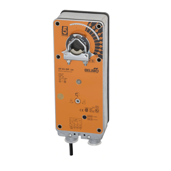
- Page 7 AF24-SR US Proportional Damper Actuator, Spring Return Fail-Safe, 24 V for 2 to 10 VDC and 4 to 20 mA Control Signal. Output Signal of 2 to 10 VDC for Position Indication. Torque min. 133 in-lb, for control of air dampers Application For proportional modulation of dampers in HVAC systems.
- Page 8 NEMA 4X housing NOTE: When using AF24-SR US actuators, only use accessories listed on this page. AF24-SR US For Actuator Wiring Information and Diagrams, Please See Belimo Wiring Guide (pg 349). 2 to 10 VDC control Typical Specification Spring return control damper actuators shall be direct coupled type which require no crankarm and linkage and be capable of direct mounting to a jackshaft up to a 1.05”...
- Page 9 AFA24-SR US Proportional Damper Actuator, Spring Return Fail-Safe 24V for 2 to 10 VDC and 4 to 20 mA Control Signal. Torque min. 133 in-lb, for control of air dampers Application For proportional modulation of dampers in HVAC systems. Actuator sizing should be done in accordance with the damper manufacturer’s specifications.
- Page 10 Actuators shall be UL Approved and CSA certified, have a 5 year warranty, and be manufac- 4 to 20 mA control tured under ISO 9001 International Quality Control Standards. Actuators shall be as manufactured by Belimo. 800-543-9038 USA 866-805-7089 CANADA 203-791-8396 LATIN AMERICA...
- Page 11 AF24-ECON-R03 US Proportional Damper Actuator, Spring Return Safety, 24V for Stand-alone Economizer Damper Control using 3 k Mixed Air Sensor, Built-in Minimum Position Adjustment. Output Signal of 2 to 10VDC for Position Indication. Application For proportional control of mixed air setpoint on economizer dampers in HVAC systems.
- Page 12 Actuators shall be cUL Approved, have a 5 year warranty, and be manufactured under ISO 9001 International Quality Control Standards. Actuators shall be as manufactured by Belimo. Override control Wire Input Signal...
- Page 13 AF24-PC US Proportional Damper Actuator, Spring Return Fail-Safe, 24 V for 0 to 20 V Phasecut Control Signal Output Signal of 2 to 10 VDC for Position Indication Torque min. 133 in-lb, for control of air dampers Application For proportional modulation of dampers in HVAC systems. Actuator sizing should be done in accordance with the damper manufacturer’s specifications.
- Page 14 NEMA 4X housing NOTE: When using AF24-PC US actuators, only use accessories listed on this page. For Actuator Wiring Information and Diagrams, Please See Belimo Wiring Guide (pg 349). Typical Specification Spring return control damper actuators shall be direct coupled type which require no crankarm and linkage and be capable of direct mounting to a jackshaft up to a 1.05”...
- Page 15 AF24-MFT (-S) US ® Proportional Damper Actuator, Spring Return Fail-Safe, Multi-Function Technology Application For proportional modulation of dampers and control valves in HVAC systems. The AF24-MFT US provides mechanical spring return operation for reliable fail- safe application. Default/Configuration Default parameters for 2 to 10 VDC applications of the AF24-MFT US actuator are assigned during manufacturing.
- Page 16 AF24-MFT (-S) US ® Proportional Damper Actuator, Spring Return Fail-Safe, Multi-Function Technology Wiring Diagrams Provide overload protection and disconnect as required. CAUTION Equipment damage! Actuators may be connected in parallel if not mechanically mounted to the same shaft. Power consumption and input impedance must be observed. Actuators may also be powered by 24 VDC.
- Page 17 AF24-MFT95 US Proportional Damper Actuator, Spring Return Fail-Safe, 24 V for Use with Honeywell® Electronic Series 90, or a 0 to 135 input input, or Honeywell series 90 (fixed) Application For proportional modulation of dampers and control valves in HVAC systems. The AF24-MFT95 US provides mechanical spring return operation for reliable fail- safe application.
- Page 18 AF24-MFT95 US Proportional Damper Actuator, Spring Return Fail-Safe, 24 V for Use with Honeywell® Electronic Series 90, or a 0 to 135 input Proportional Potentiometric Control - Wiring Diagrams WARNING Live Electrical Components! During installation, testing, servicing and troubleshooting of this product, it maybe necessary to work with live electrical components.
- Page 19 Installation Instructions Quick-Mount Visual Instructions for Mechanical Installation Quick-Mount Visual Instructions 1. Rotate the damper to its fail-safe position. If the shaft rotates counterclockwise, mount the “CCW” side of the actuator out. If it rotates clockwise, mount the actuator with the “CW” side out. 2.
- Page 20 For new construction work, order dampers with extended shafts. Instruct the 6. Slide the actuator over the shaft. installing contractor to allow space for mounting and service of the Belimo actuator 7. Position the actuator in the desired location. on the shaft. The damper shaft must extend at least 3 1/2” from the duct. If the 8.
- Page 21 Installation Instructions Mechanical Installation Short Shaft Installation If the shaft extends at least 3/4” from the duct, follow these steps: Correct clamp mounting 1. Determine the best orientation for the universal clamp on the back of the position if actuator is at full fail-safe.
- Page 22 Installation Instructions Mechanical Installation Rotation Limitation Screw secured at Secure angle-of- The angle of rotation limiter, ZDB-AF2 US, is used in conjunction with the tab on these cross hairs rotation limiter the universal clamp or IND-AF2 position indicator which comes with the ZDB-AF2 US.
- Page 23 Installation Instructions Mechanical Installation Manual Override Auxiliary Switches The AF series actuators can be manually positioned to ease installation or for The AF series actuators may be ordered with 2 built-in SPDT auxiliary switches emergency positioning. used for safety interfacing or signalling, for example, for fan start-up. The switch position near the fail-safe position is fixed at 5°.
- Page 24 Installation Instructions Non-direct Mounting Methods KH-AF Crankarm Including Retaining Ring CAUTION: The retaining clip supplied with the clamp is not used to mount the KH-AF crankarm. The KH-AF (-1) crankarm is used in non-direct coupled mounting applications. The KH-AF (-1) may also be used to simultaneously direct couple to a damper shaft and provide an additional crank arm connection to a second damper.
- Page 25 ASIC circuit developed by control signal due to control signal instability. Belimo. Unlike the conventional DC motor, there are no brushes to wear or commutators to foul. AF Actuator responds to a 80 mV signal...
- Page 26 350 Ft ÷ 3 Actuators = 117 Ft. Maximum wire run Always read the controller manufacturer's installation literature carefully MAXIMUM WIRE LENGTH before making any connections. Follow all instructions in this literature. If you have any questions, contact the controller manufacturer and/or Belimo. Wire Size Max. Feet. Wire Size Max.
- Page 27 Check that the transformer(s) are sized properly. transformer and all No. 2 wires to the other leg of the transformer. NOTE 2 If failure occurs within 5 years from original installation date, notify Belimo and give details of the application. 800-543-9038 USA 866-805-7089 CANADA...
Need help?
Do you have a question about the AF24 US and is the answer not in the manual?
Questions and answers