Advertisement
Table of Contents
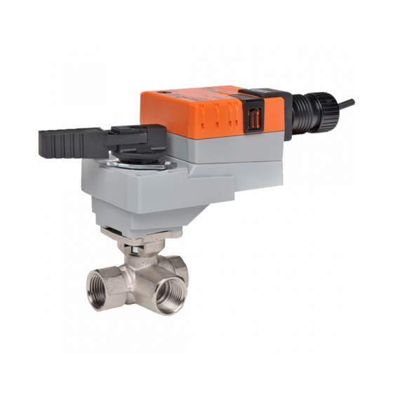
LR...24-SR Actuators, Proportional
Models
LRB24-SR-T
LRX24-SR-T
w/Terminal Block
LRB24-SR
LRX24-SR
w/3ft. cable
Technical Data
Power supply
24 VAC ± 20% 50/60 Hz
24 VDC ± 10%
Power consumption
running 1.5 W
holding 0.4 W
Transformer sizing
3 VA (class 2 power source)
Electrical connection
½" conduit connector
18 GA, plenum rated cable
LRB24-SR
3 ft [1m]
LRX24-SR
3 ft [1m], 10 ft [3m], 16 ft [5m]
Overload protection
electronic throughout 0° to 95° rotation
Operating range Y
2 to 10 VDC, 4 to 20 mA
Feedback output U
1 to 10 VDC, max 0.5 mA
100 kΩ (0.1 mA), 500 Ω
Input impedance
Angle of rotation
90°, adjustable with mechanical stop
Direction of rotation
reversible with protected
Position indication
handle
Manual override
external push button
Running time
constant independent of load
LRB24-SR
90 seconds
LRX24-SR
150, 95, 60, 45, 35 seconds
Humidity
5 to 95% RH non-condensing
(EN 60730-1)
Ambient temperature
-22°F to 122°F [-30°C to 50°C]
Storage temperature
-40°F to 176°F [-40°C to 80°C]
Housing
NEMA 2/IP54
Housing material
UL94-5VA
Agency listings†
cULus according to UL 60730-1A/-2-14,
CAN/CSA E60730-1:02, CE according to
2004/108/EC and 2006/95/EC for line voltage
and/or –S versions
Noise level
<35 dB(A)
Quality standard
ISO 9001
LR...24-SR-T
Electrical connection
screw terminal (for 26 to 14 GA wire)
protected (NEMA 2/IP20)
† Rated impulse voltage 800V, Control pollution degree 3, Type of action 1
(1.B for -S models)
800-543-9038 USA
22
Dimensions
866-805-7089 CANADA
203-791-8396 LATIN AMERICA
Advertisement
Table of Contents

Subscribe to Our Youtube Channel
Related Manuals for Belimo LRX24-SR-T


Summary of Contents for Belimo LRX24-SR-T
- Page 1 LR...24-SR Actuators, Proportional Dimensions Models LRB24-SR-T LRX24-SR-T w/Terminal Block LRB24-SR LRX24-SR w/3ft. cable Technical Data Power supply 24 VAC ± 20% 50/60 Hz 24 VDC ± 10% Power consumption running 1.5 W holding 0.4 W Transformer sizing 3 VA (class 2 power source) Electrical connection ½”...
- Page 2 LR...24-SR Actuators, Proportional Wiring Diagrams CAUTION Equipment damage! Actuators may be connected in parallel. Power consumption and input impedance must be observed. Actuators may also be powered by 24 VDC. Only connect common to neg. (–) leg of control circuits. 2 to 10 VDC control Meets cULus or UL and CSA requirements without the need of an electrical ground connection.
Need help?
Do you have a question about the LRX24-SR-T and is the answer not in the manual?
Questions and answers