
Subscribe to Our Youtube Channel
Related Manuals for Baumer TDP 0,2+OG 9


Summary of Contents for Baumer TDP 0,2+OG 9
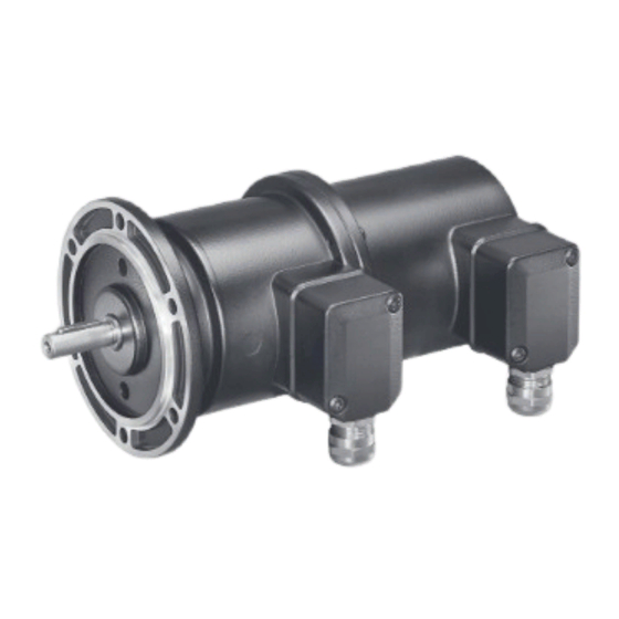
- Page 1 Montage- und Betriebsanleitung Installation and operating instructions TDP 0,2 + OG 9, TDPZ 0,2 + OG 9 Tachogenerator mit integriertem Drehgeber Tachogenerator with integrated encoder...
-
Page 2: Table Of Contents
Schritt 4 ........................9 Version mit Gehäusefuß - B3 ........................4.3.1 Schritt 2 ........................10 4.3.2 Schritt 3 ........................10 Max. zulässige Anbaufehler unter Verwendung der Baumer Hübner Federscheiben-Kupplung K 35 ................Anbauhinweis ..............................Abmessungen ................................TDP 0,2 + OG 9 ............................... - Page 3 4.2.3 Step 4 ........................9 4.3 Version with housing foot - B3 ......................... 4.3.1 Step 2 ........................10 4.3.2 Step 3 ........................10 Max. permissible mounting tolerance when the Baumer Hübner K 35 spring disk coupling is used ................ Mounting instruction ............................Dimensions ..................................5.1 TDP 0,2 + OG 9 ............................... 5.1.1 Version with EURO flange - B10 ................13 5.1.2 Version with housing foot - B3 ................13 5.2...
-
Page 4: Allgemeine Hinweise
Allgemeine Hinweise Allgemeine Hinweise Zeichenerklärung: Gefahr Warnung bei möglichen Gefahren Hinweis zur Beachtung Hinweis zur Gewährleistung eines einwandfreien Betriebes des Produkts Information Empfehlung für die Produkthandhabung Die Kombination TDP 0,2 + OG 9, TDPZ 0,2 + OG 9 ist ein generatorisch arbeitendes Prä zi- sions-Drehzahlmessgerät mit inkrementalen Drehgeber, das mit Sorgfalt nur von technisch qualifiziertem Per sonal gehandhabt werden darf. -
Page 5: General Notes
General notes General notes Symbol guide: Danger Warnings of possible danger General information for attention Informations to ensure correct product operation Information Recommendation for product handling The combination TDP 0,2 + OG 9, TDPZ 0,2 + OG 9 is a generator-based working precision rotary measurement device with incremental encoder which must be handled with care by skilled personnel only. -
Page 6: Sicherheitshinweise
Sicherheitshinweise Sicherheitshinweise Verletzungsgefahr durch rotierende Wellen Haare und Kleidungsstücke können von rotierenden Wellen erfasst werden. Vor allen Arbeiten alle Betriebsspannungen ausschalten und Maschinen stillsetzen. • Zerstörungsgefahr durch elektrostatische Aufladung Die elektronischen Bauteile in der Kombination sind empfindlich gegen hohe Spannungen. Steckkontakte und elektronische Komponenten nicht berühren. -
Page 7: Security Indications
Security indications Security indications Risk of injury due to rotating shafts Hair and clothes may become tangled in rotating shafts. Before all work switch off all operating voltages and ensure machinery is stationary. • Risk of destruction due to electrostatic charge Electronic parts contained in the encoder are sensitive to high voltages. Do not touch plug contacts or electronic components. •... -
Page 8: Vorbereitung
Vorbereitung / Preparation Vorbereitung Preparation Lieferumfang - Gerät Scope of delivery - device Gehäuse Tachogenerator Housing tachogenerator Gehäuse Drehgeber Housing encoder Vollwelle mit Passfeder Solid shaft with key EURO-Flansch - B10 EURO flange - B10 Gehäusefuß - B3 Housing foot - B3 Kohlebürstenhalterung mit Kohlebürsten Holder for carbon brushes with carbon brushes Kohlebürsten, auch als Zubehör erhältlich, Carbon brushes, also available as accessory, Bestellnummer 11076778 (S7/H7) order number 11076778 (S7/H7) Abdeckung für Kohlebürsten Cover for carbon brushes... -
Page 9: Lieferumfang - Klemmenkästen
Vorbereitung / Preparation Lieferumfang - Klemmenkästen Scope of delivery - terminal boxes Klemmenkasten Tachogenerator Terminal box tachogenerator Klemmenkastendeckel Terminal box cover Kombi-Torx-Schraube M4x32 mm Screw with torx and slotted drive M4x32 mm Kabelverschraubung M20x1,5 Cable gland M20x1,5 für Kabel ø5-13 mm for cable ø5-13 mm Anschlussklemmen, Connecting terminal, siehe Abschnitt 6.1. -
Page 10: Zur Montage Erforderlich (Nicht Im Lieferumfang Enthalten)
Vorbereitung / Preparation Zur Montage erforderlich Required for mounting (nicht im Lieferumfang enthalten) (not included in scope of delivery) Anbauvorrichtung, kundenspezifisch Installation fitting, customized Befestigungsschrauben für Anbauvorrichtung Fixing screws for installation fitting ISO 4017, ISO 4017, M6x16 mm M6x16 mm Federscheibenkupplung K 35, Spring disk coupling K 35, als Zubehör erhältlich, siehe Abschnitt 4.4. available as accessory, see section 4.4. -
Page 11: Montage
Montage / Mounting Montage Mounting Schritt 1 Step 1 Zul. Anzugsmoment Max. tightening torque = 2-3 Nm 2.5 mm Version mit EURO-Flansch - B10 Version with EURO flange - B10 4.2.1 Schritt 2 4.2.1 Step 2 10 mm * Siehe Seite 7 See page 7 Motorwelle einfetten! Lubricate motor shaft! -
Page 12: Schritt 3
Montage / Mounting 4.2.2 Schritt 3 4.2.2 Step 3 10 mm 4.2.3 Schritt 4 4.2.3 Step 4 2.5 mm Zul. Anzugsmoment Max. tightening torque = 2-3 Nm * Siehe Seite 5 oder 7 See page 5 or 7 MB079.3 - 11130053 ... -
Page 13: Version Mit Gehäusefuß - B3
Montage / Mounting Version mit Gehäusefuß - B3 Version with housing foot - B3 4.3.1 Schritt 2 4.3.1 Step 2 Motorwelle einfetten! Lubricate motor shaft! Die Antriebswelle sollte einen mög- The drive shaft should have as less lichst kleinen Rundlauffehler aufwei- runout as possible. -
Page 14: Max. Zulässige Anbaufehler Unter Verwendung Der Baumer Hübner Federscheiben-Kupplung K 35
K 35 spring disk coupling is used Kombinationen mit Vollwelle sollten Combinations with a solid shaft should be unter Verwendung der Baumer Hübner driven through the Baumer Hübner K35 Federscheiben-Kupplung K35 (Zubehör) spring disk coupling (accessory), that can angetrieben werden, die sich ohne axialen be pushed onto the shaft without axial Druck auf die Welle schieben lässt. -
Page 15: Anbauhinweis
Montage / Mounting Anbauhinweis Mounting instruction Wir empfehlen, die Kombination so zu It is recommended to mount the montieren, dass der Kabelanschluss combination with cable connection keinem direkten Wassereintritt aus- facing downward and being not expo- gesetzt ist. sed to water. MB079.3 - 11130053 Baumer_TDP02-OG9-TDPZ02-OG9_II_DE-EN (14A1) ... -
Page 16: Abmessungen
Abmessungen / Dimensions Abmessungen Dimensions TDP 0,2 + OG 9 TDP 0,2 + OG 9 5.1.1 Version mit EURO-Flansch - B10 5.1.1 Version with EURO flange - B10 (61363, 61373) (61363, 61373) Drehrichtung positiv Positive rotating direction 5.1.2 Version mit Gehäusefuß - B3 5.1.2 Version with housing foot - B3 (61257) -
Page 17: Tdpz 0,2 + Og 9 (Doppel-Tachogenerator)
Abmessungen / Dimensions TDPZ 0,2 + OG 9 TDPZ 0,2 + OG 9 (Doppel-Tachogenerator) (twin tachogenerator) 5.2.1 Version mit EURO-Flansch - B10 5.2.1 Version with EURO flange - B10 (61807, 61815) (61807, 61815) Drehrichtung positiv Positive rotating direction 5.2.2 Version mit Gehäusefuß - B3 5.2.2 Version with housing foot - B3 (61510) -
Page 18: Elektrischer Anschluss
Elektrischer Anschluss / Electrical connection Elektrischer Anschluss Electrical connection Tachogenerator Tachogenerator 6.1.1 Kabelanschluss 6.1.1 Cable connection TX 20 22 mm 12c * ø5-13 mm Ansicht siehe Abschnitt 6.1.2 und 6.1.3. View , see section 6.1.2 and 6.1.3. Zur Gewährleistung der angege- To ensure the specified protection benen Schutzart sind nur geeignete of the device the correct cable dia- Kabeldurchmesser zu verwenden. -
Page 19: Drehgeber Og 9
Elektrischer Anschluss / Electrical connection Drehgeber OG 9 Encoder OG 9 6.2.1 Kabelanschluss 6.2.1 Cable connection TX 20 22 mm 13c * ø5-13 mm Ansicht siehe Abschnitt 6.2.2. * Siehe Seite 6 View , see section 6.2.2. See page 6 Zur Gewährleistung der angege- To ensure the specified protection benen Schutzart sind nur geeignete of the device the correct cable dia- Kabeldurchmesser zu verwenden. -
Page 20: Ausgangssignale
Sensorkabel HEK 8 (Zubehör) 6.2.4 Sensor cable HEK 8 (accessory) Es wird empfohlen, das Baumer Hübner Baumer Hübner sensor cable HEK 8 is Sensorkabel HEK 8 zu verwenden oder recommended. As a substitute a shielded ersatzweise ein geschirmtes, paarig ver- twisted pair cable should be used. -
Page 21: Betrieb Und Wartung
Betrieb und Wartung / Operation and maintenance Betrieb und Wartung Operation and maintenance Austausch der Kohlebürsten Replace of the carbon brushes Bei Erreichen der minimalen Bürstenlänge When the minimum brush length (L) of (L) von 5,3 mm sollten die Bürsten ausge- 5.3 mm is reached , the brushes should be wechselt sowie der Kommutatorraum mit replaced and the commutator area should trockener Pressluft ausgeblasen werden, be cleaned with dry compressed air in or-... -
Page 22: Demontage
Demontage / Dismounting Demontage Dismounting Schritt 1 Step 1 TX 20 13c * 22 mm Schritt 2 Step 2 TX 20 22 mm * Siehe Seite 6 oder 7 See page 6 or 7 MB079.3 - 11130053 Baumer_TDP02-OG9-TDPZ02-OG9_II_DE-EN (14A1) - Page 23 Demontage / Dismounting Schritt 3 Step 3 8.3.1 Version mit EURO-Flansch - B10 8.3.1 Version with EURO flange - B10 10 mm 2.5 mm 8.3.2 Version mit Gehäusefuß - B3 8.3.2 Version with housing foot - B3 2.5 mm 10 mm Schritt 4 Step 4 8.4.1 Version mit EURO-Flansch - B10...
-
Page 24: Zubehör
Demontage - Zubehör / Dismounting - Accessories Schritt 4 Step 4 8.4.2 Version mit Gehäusefuß - B3 8.4.2 Version with housing foot - B3 Schritt 5 Step 5 2.5 mm * Siehe Seite 7 See page 7 Zubehör Accessories Federscheiben-Kupplung Spring disk coupling • • K 35 K 35 Sensorkabel für Drehgeber Sensor cable for encoders... -
Page 25: Anhang: Eu-Konformitätserklärung
Anhang: EU-Konformitätserklärung / Appendix: EU Declaration of conformity Anhang: Appendix: EU-Konformitätserklärung EU Declaration of conformity MB079.3 - 11130053 Baumer_TDP02-OG9-TDPZ02-OG9_II_DE-EN (14A1) ... -
Page 26: Technische Daten
Technische Daten Technische Daten 11.1 Technische Daten - elektrisch Störfestigkeit: EN 61000-6-2:2005 • Störaussendung: EN 61000-6-3:2007/A1:2011 • Zulassungen: CE, RoHS • 11.2 Technische Daten - elektrisch (Tachogenerator) Reversiertoleranz: ≤0,1% • Linearitätstoleranz: ≤0,15% • Temperaturkoeffizient: ±0,05%/K (Leerlauf) • Isolationsklasse: • Kalibriertoleranz: ±1% •... -
Page 27: Daten Nach Typ
TDP 0,2 + OG 9 Trägheitsmoment Rotor: 1,4 kgcm² • Masse ca.: 3,3 kg • TDPZ 0,2 + OG 9 Trägheitsmoment Rotor: 1,5 kgcm² • Masse ca.: 3,5 kg • 11.5 Daten nach Typ Leerlauf- Min. erforderlicher Lastwiderstand in Max. Anker- Anker- spannung... -
Page 28: Technical Data
Technical data Technical data 11.1 Technical data - electrical ratings Interference immunity: EN 61000-6-2:2005 • Emitted interference: EN 61000-6-3:2007/A1:2011 • Approvals: CE, RoHS • 11.2 Technical data - electrical ratings (tachogenerator) Reversal tolerance: ≤0.1% • Linearity tolerance: ≤0.15% • Temperature coefficient: ±0.05%/K • Isolation class: • Calibration tolerance: ±1 % • Climatic test: Humid heat, constant (IEC 60068-2-3, Ca) •... -
Page 29: Type Data
TDP 0,2 + OG 9 Rotor moment of inertia: 1.4 kgcm² • Weight approx.: 3.3 kg • TDPZ 0,2 + OG 9 Rotor moment of inertia: 1.5 kgcm² • Weight approx.: 3.5 kg • 11.5 Type data Open- Minimum load required Maximum Armature Armature circuit depending on speed range operating resistance inductance voltage [rpm] speed... - Page 30 MB079.3 - 11130053 Baumer_TDP02-OG9-TDPZ02-OG9_II_DE-EN (14A1)
- Page 31 MB079.3 - 11130053 Baumer_TDP02-OG9-TDPZ02-OG9_II_DE-EN (14A1)
- Page 32 Baumer Hübner GmbH P.O. Box 12 69 43 · 10609 Berlin, Germany Phone: +49 (0)30/69003-0 · Fax: +49 (0)30/69003-104 info@baumerhuebner.com · www.baumer.com/motion Version: 61257, 61363, 61373, 61510, 61807, 61815 MB079.3 - 11130053 Baumer_TDP02-OG9-TDPZ02-OG9_II_DE-EN (14A1 - 04.06.2014)
Need help?
Do you have a question about the TDP 0,2+OG 9 and is the answer not in the manual?
Questions and answers