Sign In
Upload
Download
Table of Contents
Contents
Add to my manuals
Delete from my manuals
Share
URL of this page:
HTML Link:
Bookmark this page
Add
Manual will be automatically added to "My Manuals"
Print this page
×
Bookmark added
×
Added to my manuals
Manuals
Brands
Baumer Manuals
Measuring Instruments
PAC50H
Operating manual
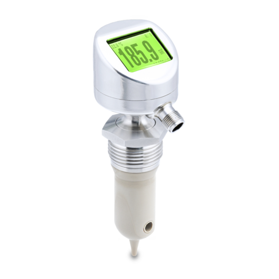
Baumer PAC50H Operating Manual
Hide thumbs
1
Table Of Contents
2
3
4
5
6
7
8
9
10
11
12
13
14
15
16
17
18
19
20
21
22
23
24
25
26
27
28
29
30
31
32
33
34
35
36
37
38
39
40
41
42
43
44
page
of
44
Go
/
44
Contents
Table of Contents
Troubleshooting
Bookmarks
Table of Contents
Table of Contents
About this Document
Purpose
Warnings in this Manual
Labels in this Manual
Scope of Delivery
Name Plate
Accessories
Ill. 1 Name Plate
General Information
Security
Description
Structure
Product Versions
Ill. 2 Structure
Functional Description
Operating and Display Elements
Ill. 3 Functional Description (Schematic)
Transport and Storage
Transport
Delivery Inspection
Storage
Installation
Introduction
Mounting Prerequisites
Installation Positions
Installation Factor
Mounting the Sensor
Mounting Example with Weld-In Socket ZPW2-521
Certifications
Electrical Installation
Pin Assignment
Electrical Connection
Commissioning
Commissioning- Preamble
Factory Settings
Parameterization Using the Integrated Display
Select Language, Example
Example Change Display Orientation
Parameterization Via Flexprogram
Parameterization Via IO-Link Master
Media Calibration
Description Display
Display Status Bar
Display Screen Layout
Ill. 4 Display
Display Menu Navigation
Menu Structure
Submenu Basic Setup
Submenu Input Setup
Submenu Output Setup
Submenu Switch Setup
Submenu Display Setup
Submenu Calibration
Submenu Identification
Submenu Diagnostics
Preventive Maintenance
Maintenance Chart
Cleaning the Sensor
Sensor Calibration
Sensor Calibration with the Aid of a Reference Sensor
Sensor Calibration with the Aid of a Reference Medium
Sensor Calibration Using the Baumer Calibration Box
Reset User Calibration
Troubleshooting
Error Messages
Error Alarms
Return and Repair
Glossary
Advertisement
Quick Links
Download this manual
Operating Manual
PAC50H/S
EN-US
Conductivity measurement
Table of
Contents
Previous
Page
Next
Page
1
2
3
4
5
Advertisement
Table of Contents
Need help?
Do you have a question about the PAC50H and is the answer not in the manual?
Ask a question
Questions and answers
Related Manuals for Baumer PAC50H
Measuring Instruments Baumer HUBNER POG 10 + ESL Mounting And Operating Instructions
Incremental encoder with integrated electronic speed switch (36 pages)
Measuring Instruments Baumer PAC50S Operating Manual
(44 pages)
Measuring Instruments Baumer CleverLevel PL20H/S Operating Instructions Manual
Level measurement adaptive trigger – hygienic/industrial (44 pages)
Measuring Instruments Baumer GCA5 C8 Manual
Cable transducer gca5 with canopen (16 pages)
Measuring Instruments Baumer N 208 Operating Instructions Manual
Totalizer (36 pages)
Measuring Instruments Baumer OM20 IO-Link Operating Manual
Laser distance sensor (52 pages)
Measuring Instruments Baumer CombiLyz AFI4 Operating Instructions Manual
Conductivity measurement inductive conductivity transmitter (52 pages)
Measuring Instruments Baumer TA202 Operating Instructions Manual
Electronic tachometer (52 pages)
Measuring Instruments Baumer TER8 Operating Instructions Manual
Temperature measurement, front-flush and low-invasive resistance thermometers (28 pages)
Measuring Instruments Baumer VCXG.2-13M Operating Manual
(218 pages)
Measuring Instruments Baumer CleverLevel LBFH/I Operating Instructions Manual
Point level detection – hygienic/industrial level measurement (48 pages)
Measuring Instruments Baumer CX Series Operating Manual
(220 pages)
Measuring Instruments Baumer CTX User Instructions
(2 pages)
Measuring Instruments Baumer TA201 Operating Instructions Manual
Electronic (36 pages)
Measuring Instruments Baumer Hubner HENQ 1100 Operating Instructions Manual
Encoder analyzer (36 pages)
Measuring Instruments Baumer FKDM 22P1901/S14F User Manual
Photo electric sensor (4 pages)
This manual is also suitable for:
Pac50s
Table of Contents
Print
Rename the bookmark
Delete bookmark?
Delete from my manuals?
Login
Sign In
OR
Sign in with Facebook
Sign in with Google
Upload manual
Upload from disk
Upload from URL


Need help?
Do you have a question about the PAC50H and is the answer not in the manual?
Questions and answers