Table of Contents
Advertisement
Quick Links
Advertisement
Table of Contents

Related Manuals for Roland V-1HD+


Summary of Contents for Roland V-1HD+
- Page 1 Reference Manual © 2020 Roland Corporation...
- Page 2 5 Roland is an either registered trademark or trademark of Roland Corporation in the United States and/or other countries. 5 Company names and product names appearing in this document are registered trademarks or trademarks of their respective owners.
-
Page 3: Table Of Contents
Contents Panel Descriptions Audio Operations Top Panel Adjusting the Input Gain (Sensitivity) Rear Panel (Connecting Your Equipment) Adjusting the Volume Balance Side Panel (Connecting Your Equipment) Applying Effects to Input Audio Multi-View Display Applying Effects to Output Audio Interlinking Audio Output to Video Switching (Audio Follow) Basic Operations Checking a Specific Audio Input (Solo) Turning the Power On/Off... -
Page 4: Panel Descriptions
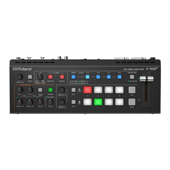
Panel Descriptions Top Panel [OUTPUT FADE] knob USER (p. 23) (p. 29, 30) The final output video and audio fade in/out. [DSK PVW] button Rotating the knob counterclockwise fades to black, and rotating When this is on (lit), it makes the DSK compositing results the the knob clockwise fades to white. - Page 5 Panel Descriptions [MODE] button, [1/5]–[4/8] buttons HDCP indicator (p. 13) Use the [MODE] button to select the function of the [1/5]–[4/8] buttons. This indicator is lit, blinking, or unlit according to the An indicator located below the [MODE] button is lit to indicate the current HDCP (copy protection) setting and according to function.
-
Page 6: Rear Panel (Connecting Your Equipment)
Panel Descriptions Rear Panel (Connecting Your Equipment) * To prevent malfunction and equipment failure, always turn down the volume, and turn off all the units before making any connections. DC IN jack OUTPUT 1, 2 connectors Connect the included AC adaptor to this jack. These output video. - Page 7 Panel Descriptions * Do not block the ventilation openings (the slits located on the front and side panels, etc.). If the ventilation openings are blocked, the internal temperatures may rise, causing malfunctions due to excessive heat. AUDIO IN 1, 2 jacks/LINE IN L, R jacks Phantom power settings These input audio.
-
Page 8: Side Panel (Connecting Your Equipment)
Panel Descriptions Side Panel (Connecting Your Equipment) * To prevent malfunction and equipment failure, always turn down the volume, and turn off all the units before making any connections. MIC/AUX IN jack This inputs audio. Connect a mic, audio mixer, CD players, or Plug-in Power settings other such audio equipment. -
Page 9: Multi-View Display
If a camera that supports the REC status 5 For details on the cameras that support the REC status function is connected, this is shown function, refer to the Roland website. when the camera’s REC button is pressed. https://proav roland com/ PinP indicator 5 The menu is shown on the monitor that’s connected to the... -
Page 10: Basic Operations
Basic Operations Turning the Power On/Off Operating the Menu Once everything is properly connected, be sure to follow the Here’s how to access the menu, and make video/audio settings and procedure below to turn on their power. If you turn on equipment in settings for this unit. -
Page 11: Video Input/Output Settings
Video Input/Output Settings Setting the Video Input/Output Format Here’s how to specify the input/output format as appropriate for the device that’s connected. Setting the System Format Setting the Input Format for the INPUT 4 Connector On this unit, the input/output format is determined according to With the factory settings, the EDID assignment for the INPUT 4 the system format. -
Page 12: Adjusting Output Video
Video Input/Output Settings Adjusting Output Video Adjusting Input Video Here’s how to adjust the output image appropriately for the device Here’s how to adjust the quality of the input video signals. that’s receiving the unit’s output. For the INPUT 4 connector, you can also adjust the scaling. [MENU] button 0 “VIDEO OUTPUT”... -
Page 13: Changing Output Bus Assignments
Video Input/Output Settings Changing Output Bus Assignments Inputting Copy-Protected (HDCP) Video This unit provides three output buses: PROGRAM, PREVIEW, and If you want to input HDCP-protected video from a BD player or other MULTI-VIEW. You can assign the output bus of your choice to each of device, you can enable HDCP input. -
Page 14: Video Operations
Video Operations Switching the Video You can switch between the videos of the A/PGM bus and B/PST bus to specify the final output. Setting the Operation Mode Switching in the A/B Mode There are two operation modes for switching the video: the “A/B Here are the steps when selecting “A/B mode”... -
Page 15: Switching In The Pgm/Pst Mode
Video Operations <Using the fader to switch> Switching in the PGM/PST Mode Slide the video fader in the direction opposite to the Here are the steps when selecting “PGM/PST mode” in the operation direction in step 1. mode settings. For more details on the operation modes, see “Setting the Operation Mode”... -
Page 16: Changing The Mix/Wipe Pattern
Video Operations <Using the fader to switch> Changing the Mix/Wipe Pattern Slide the video fader in the direction opposite to the You can change the transition pattern by which the mix/wipe occurs direction in step 1. and the direction of the wipe. The transition indicator on the bus side [MENU] button 0 select “MIX/WIPE,”... -
Page 17: Changing The Functions Of The [Cut] And [Auto] Buttons
Video Operations Changing the Functions of the [CUT] and [AUTO] Buttons You can change what happens when you press the [CUT] and [AUTO] buttons. * In PGM/PST mode (p. 15), the functions of the [CUT] and [AUTO] buttons are fixed. [MENU] button 0 “SYSTEM”... -
Page 18: Switching The Video Automatically (Auto Switching)
Video Operations Switching the Video Automatically (Auto Switching) The video of INPUT 1–4 or of preset memories (p. 38) can be switched automatically (the auto switching function). * You can make operation easier by letting the video switch automatically. About the Operation Mode Setting the Operation Mode Auto switching provides three operation modes that you can select Input scan... - Page 19 Video Operations Preset memory scan BPM sync [MENU] button 0 “AUTO SWITCHING” 0 select “TYPE,” [MENU] button 0 “AUTO SWITCHING” 0 select “TYPE,” and press the [VALUE] knob. and press the [VALUE] knob. Use the [VALUE] knob to select “PRESET MEMORY SCAN,” Use the [VALUE] knob to select “BPM SYNC,”...
-
Page 20: Loading A Still Image
Video Operations Loading a Still Image You can load a still image, and output it in the same way as video (p. 22) or use it as a source for DSK compositing (p. 29). There are two ways to load a still image: you can load from a USB flash drive, or you can capture from input video. You can save up to four still images in the unit. -
Page 21: Capturing A Still Image From Input Video
Video Operations Capturing a Still Image from Input Video Deleting a Still Image Here’s how to capture a still image from the input video. Here’s how to delete the still image that’s saved in the unit. [MENU] button 0 “STILL IMAGE” 0 select “DELETE STILL NOTE IMAGE,”... -
Page 22: Outputting A Loaded Still Image
Video Operations Outputting a Loaded Still Image You can assign a still image to INPUT 1–4 and output it in the same way as with video, or momentarily stop the final output to output the still image. Assigning Still Images to INPUT 1–4 Inserting a Still Image in the Final Output A still image loaded into this unit can be assigned to the video source You can pause the final output, and output a still image of your choice. -
Page 23: Fading-In/Out The Final Output Video
Video Operations Fading-In/Out the Final Output Video Freezing the Input Video (Freeze) Here’s how to perform a fade-out from the final output video to a Here’s how to temporarily freeze the input video (freeze function). black/white screen, or a fade-in from a black/white screen to the final You can apply transition effects during a video freeze. -
Page 24: Video Composition Operations
Video Composition Operations Compositing Video with Split Here’s how to composite two videos in dividing the screen into left/right or upper/lower. 7 Positioning a video Use the [CONTROL 1] and [CONTROL 2] knob to adjust Left or upper: Video on the A/PGM bus the position of the video or boundary. -
Page 25: Compositing Video With Picture-In-Picture (Pinp)
Video Composition Operations Compositing Video with Picture-in-Picture (PinP) Here’s how to composite an inset screen (a small separate screen) onto the background video. Inset screen Sending the Inset Screen to Final Output Immediately Here are the steps when selecting “PVW.PGM mode” in the operation Background video mode settings. -
Page 26: Checking The Composited Result For Final Output
Video Composition Operations Checking the Composited Result for Final Output MEMO 5 Set the fade-in/out time for the inset screen from the [MENU] Here are the steps when selecting “PVW mode” in the operation button 0 “TRANSITION” 0 “PinP TIME. ” mode settings. -
Page 27: Making Detailed Settings For The Inset Screen
Video Composition Operations Press the [AUTO] or [CUT] button to switch the video. Making Detailed Settings for the Inset Screen Detailed settings for size, shape, and border width etc. can be made for the inset screens. [MENU] button 0 select “PinP,” and press the [VALUE] knob. -
Page 28: Key Compositing The Inset Screen
Video Composition Operations Key Compositing the Inset Screen This process makes part of the inset screen transparent, and composites the image with the background video. You can use luminance key with either a black or a white background, or a chroma key with either a blue or green background. Luminance key You can cut out a logo or image by turning its black or white portion transparent, and then superimpose it on the background video. -
Page 29: Compositing Video With Downstream Keyer (Dsk)
Video Composition Operations Compositing Video with Downstream Keyer (DSK) This process performs key compositing on text or video downstream (DSK compositing) of a video that was already composited upstream. You can switch between background video while still displaying the text or video. With DSK composition, you can use luminance key with either a black or a white background, or a chroma key with either a blue or green background. -
Page 30: Compositing A Subject And Background (Chroma Key)
Video Composition Operations Compositing a Subject and Background (Chroma Key) Here’s how you can cut out a video by turning its blue or green portion transparent, and then superimpose it on the background video. This lets you composite a subject that’s photographed against a blue background or green background. Video to be Compositing using DSK superimposed... - Page 31 Video Composition Operations To specify a desired color as the key color (sampling marker) You can select a key color besides green or blue to use for chroma key compositing. Sample (detect) the color in the video that you wish to make transparent, and set it as the key color (this is called the sampling marker function).
-
Page 32: Audio Operations
Audio Operations Adjusting the Input Gain (Sensitivity) Here’s how to adjust the input gain so that the audio is at the appropriate level. AUDIO IN 1 and 2 MIC/AUX IN Here we explain using the AUDIO IN 1 audio as an example. Move the [MAIN] knob to a position near the indicator (0 dB). -
Page 33: Adjusting The Volume Balance
Audio Operations Adjusting the Volume Balance Here’s how to adjust the volume balance of each input and the overall volume. Level meter indication Move the [MAIN] knob to a position near the indicator (0 dB). Indicator (0 dB) The audio level meter is shown in each section of the multi-view. The level meter illumination lets you check whether the volume is adjusted appropriately. -
Page 34: Applying Effects To Input Audio
Audio Operations Applying Effects to Input Audio You can apply effects to the input audio to adjust the character of the sound. The following table shows the effects that are available. Input audio High-pass filter Noise gate De-esser Compressor Equalizer Reverb INPUT 1–4 —... -
Page 35: Applying Effects To Output Audio
Audio Operations Applying Reverb Applying Effects to Output Audio This adds reverberation to the sound. Here’s how to modify the tonal character by applying effects to the audio output. You can use limiter, compressor, and equalizer. Adjusting how much reverb to send [SETUP] button 0 select “INPUT 1”–“MIC/AUX IN, ”... -
Page 36: Interlinking Audio Output To Video Switching (Audio Follow)
Audio Operations Interlinking Audio Output to Video Checking a Specific Audio Input (Solo) Switching (Audio Follow) Here’s how you can temporarily monitor a specific audio input via the headphones (solo function). Here’s how the audio output can be automatically switched in * The solo function applies to the headphone output. -
Page 37: Silencing Only Specific Audio (Mute)
Audio Operations Silencing Only Specific Audio (Mute) Correcting a Time Difference Between Video and Audio (Delay) Here’s how you can temporarily mute specific audio (the mute function). If there is a timing discrepancy between the video and audio, you can correct the output timing by delaying the audio output. -
Page 38: Other Features
Other Features Saving/Recalling Settings (Preset Memory) You can save the current settings, including the video/audio settings and the state of the operating panel, in preset memory and recall those settings for use when necessary. This unit is provided with eight memories. About the Last Memory function This unit has a built-in Last Memory feature. -
Page 39: Formatting A Usb Flash Drive
Other Features Initializing a Preset Memory Formatting a USB Flash Drive Here’s how you can initialize the settings of a specific preset memory The first time that you use a USB flash drive, you must use this unit to to the factory-set condition. format it. -
Page 40: Backing Up And Restoring The Unit's Settings On A Usb Flash Drive
Other Features Backing Up and Restoring the Unit’s Settings on a USB Flash Drive You can group together the unit’s settings into a single file (.V1P) and back up it to a USB flash drive connected to the USB MEMORY port. You can access the backed up setting file on the USB flash drive and restore it into the unit for use when needed. -
Page 41: Assigning Different Functions To Control
Other Features Restoring Assigning Different Functions to Control with the [DSK PVW] and [DSK ON] Buttons Here’s how to restore this unit’s settings that you saved on a USB flash drive. When you restore settings, the current settings are overwritten. You can assign different functions to control with the [DSK PVW] and [DSK ON] buttons. -
Page 42: Preventing Unintended Operation (Panel Lock)
REC START/STOP on the recorder from this unit. For more about recorders that support the REC control function, [MENU] button 0 “SYSTEM” 0 select “PANEL LOCK,” and refer to the Roland website. press the [VALUE] knob. https://proav roland com/ The PANEL LOCK menu appears. -
Page 43: Returning To The Factory Settings (Factory Reset)
Other Features Returning to the Factory Settings (Factory Reset) Here’s how you can return the settings of this unit to their factory-set state. If following the procedures described in this manual does not cause the result you expect, try executing a factory reset. NOTE 5 When you execute factory reset, any previously specified content, any settings saved in preset memory (p. -
Page 44: Menu List
Menu List 1: VIDEO INPUT Menu item Value Explanation (bold text: default value) INPUT 1–3 Adjusts the video that is input from the INPUT 1–3 connectors. INPUT STATUS (*1) ENTER Displays information about the incoming video (format, size, etc.). Selects the video source for INPUT 1–3. INPUT ASSIGN HDMI The video input from the INPUT connector. -
Page 45: 2: Video Output
Menu List 2: VIDEO OUTPUT Menu item Value Explanation (bold text: default value) OUTPUT 1, 2 Adjusts the video that is output from the OUTPUT 1 and 2 connectors. OUTPUT STATUS — Shows the connection status of the OUTPUT connector. Specifies the output bus that is assigned to the OUTPUT connector. -
Page 46: 5: Split
Menu List 5: SPLIT Menu item Value Explanation (bold text: default value) Turns the split composition on/off. SPLIT OFF, ON You can also use the [ SPLIT ] button to turn this on/off. Selects the split composition types. Press and turn the [CONTROL 2] knob to switch between compositing types. (*5) This vertically crops the center section of the video. -
Page 47: 6: Pinp
Menu List 6: PinP Menu item Value Explanation (bold text: default value) Specifies the video source of the inset screen. PinP SOURCE HDMI 1–4, STILL 1–4 When the [MODE] button is lit up yellow, you can select HDMI 1–4 with the [1/5]–[4/8] buttons. - Page 48 Menu List Menu item Value Explanation (bold text: default value) If this is “MATTE, ” the superimposed logo or video is filled-in with the FILL TYPE BUS, MATTE specified color when using key compositing. The fill-in color is specified by “MATTE COLOR”...
-
Page 49: 7: Dsk
Menu List 7: DSK Menu item Value Explanation (bold text: default value) Turns the preview output of the DSK compositing result on/off. DSK PVW OFF, If “DSK PVW” function is assigned to the [DSK PVW] button, you can also switch this by pressing the button. -
Page 50: 8: Audio Input
Menu List 8: AUDIO INPUT Menu item Value Explanation (bold text: default value) INPUT 1–4 Adjusts the audio that is input from the INPUT 1–4 connectors (HDMI). DIGITAL GAIN -42.0–0 0–42.0dB Adjusts the digital gain. INPUT LEVEL -INF–0 0–10.0dB Adjusts the input volume. OFF, ON INPUT MUTE Turns the mute function on/off. - Page 51 Menu List Menu item Value Explanation (bold text: default value) Adjusts the audio that is input from the AUDIO IN 1 and 2 jacks. AUDIO IN 1, 2 AUDIO IN 1/2 (LINKED) * “AUDIO IN 1/2 (LINKED)” is shown when “SETUP (LINK) SW” is “ON. ” Adjusts the input gain (sensitivity) in the analog domain.
- Page 52 Menu List Menu item Value Explanation (bold text: default value) LINE IN Adjusts the audio that is input from the LINE IN jacks. 0–42dB DIGITAL GAIN -42–0 Adjusts the digital gain. 0–10.0dB INPUT LEVEL -INF–0 Adjusts the input volume. INPUT MUTE OFF, ON Turns the mute function on/off.
- Page 53 Menu List Menu item Value Explanation (bold text: default value) Converts the input audio from stereo to mono. Sends the stereo input audio without change. MONO L MONO The audio of the L channel is sent to both L and R. R MONO The audio of the R channel is sent to both L and R.
-
Page 54: 9: Audio Output
Menu List 9: AUDIO OUTPUT Menu item Value Explanation (bold text: default value) MAIN OUTPUT Adjusts the audio that is output from the AUDIO OUT jacks. Adjusts the output volume. OUTPUT LEVEL 0–10.0dB -INF–0 This can also be adjusted by the [MAIN] knob. Turns the mute function on/off. -
Page 55: 10: Audio Follow
Menu List 10: AUDIO FOLLOW Menu item Value Explanation (bold text: default value) ALL AUDIO FOLLOW OFF, ON Turns on/off the audio follow function for INPUT 1–4 in a single action. Turns the audio follow function on/off. Audio follow is a function that automatically switches the audio output in tandem with video switching. -
Page 56: 12: Capture Image
Menu List 12: CAPTURE IMAGE Menu item Value Explanation (bold text: default value) Specifies where to save still images imported from a USB flash drive to this unit’s internal memory. Press the [VALUE] knob to load the still images. * An internal memory in which a still image is loaded is indicated by a “ ” symbol. Formats supported for loading Windows Bitmap file (.bmp), 24-bit color, uncompressed LOAD FROM USB MEMORY... -
Page 57: 14: Auto Switching
Menu List 14: AUTO SWITCHING Menu item Value Explanation (bold text: default value) Turns the auto switching function on/off. If this is “ON, ” the video or preset memory are switched AUTO SWITCHING OFF, ON automatically. Specifies the operation mode for auto switching. INPUT SCAN Automatically switches to the video of INPUT 1–4 when the specified interval. -
Page 58: 16: Tally
Menu List 16: TALLY/RS-232 Menu item Value Explanation (bold text: default value) Turns the tally signal output on/off. If this is “ON, ” , the tally signal is output from the TALLY TALLY OFF, connector (p. 67). RS-232 OFF, If this is “ON, ” RS-232 commands can be transmitted and received. RATE 38400, 115200... - Page 59 Menu List Menu item Value Explanation (bold text: default value) Specifies the settings that are operated by the [CONTROL 1] and [CONTROL 2] knobs when both split and PinP compositing are on. Knob SPLIT PinP SPLIT [CONTROL 1] A-CENTER POSITION H CONTROL KNOB [CONTROL 2] B-CENTER...
- Page 60 Menu List Menu item Value Explanation (bold text: default value) AUDIO LEVEL METER OFF, Specifies whether to display the audio level meter in the multi-view. Specifies the position of the level meter for audio input from the audio jacks. AUDIO IN/LINE IN OFF, LOWER, UPPER When this is “OFF, ”...
-
Page 61: Rs-232 Command Reference
RS-232 Command Reference This unit supports remote interface communications via RS-232. Using the RS-232 connector to send specific commands to this unit from a controlling device lets you operate this unit remotely. * To send and receive RS-232 commands, press the [MENU] button, and from “TALLY/RS-232, ” set “RS-232” to “ON. ” RS-232 Interface Command Format RS-232 connector pin layout... -
Page 62: List Of Commands
RS-232 Command Reference List of Commands * When sending a sequence of commands to this unit from a controller, after each one, be sure to verify that an “ack” response is returned before sending the next command. Video operations Sent Response Item Parameter... - Page 63 RS-232 Command Reference Audio operations Sent Response Item Parameter command command Adjust the input volume level stxIAL:a,b; a = 0 (INPUT 1), 1 (INPUT 2), 2 (INPUT 3), 3 (INPUT 4), 4 (AUDIO IN 1) 5 (AUDIO IN 2), 6 (LINE IN), 7 (MIC/AUX IN) b = -801 (-INF dB), -800 (-80.0 dB)–0 (0.0 dB)–100 (10.0 dB) Adjust the output volume level stxOAL:a;...
- Page 64 RS-232 Command Reference Other operations Sent Response Item Parameter command command Select functions for buttons stxMOD:a; a = 0 (STILL IMAGE), 1 (PinP SOURCE), 2 (MEMORY 1–4), 3 (MEMORY 5–8), [1/5]–[4/8] Press button [1/5]–[4/8] stxMNS:a; a = 0 (1/5)–3 (4/8) Set HDCP on/off stxHCP:a;...
-
Page 65: Appendices
Appendices Main Specifications 9 Video Video Processing 4:2:2 (Y/Pb/Pr), 8-bit HDMI type A x 3 INPUT 1–3 * HDCP supported Input Connectors HDMI type A INPUT 4 * HDCP and multi-format supported Output Connectors OUTPUT 1, 2 HDMI type A x 2 SYSTEM FORMAT setting: 720p SYSTEM FORMAT setting: 1080i or 1080p FRAME RATE setting... - Page 66 Startup Guide, Leaflet “USING THE UNIT SAFELY, ” AC adaptor, Power cord * 0 dBu = 0.775 Vrms * This document explains the specifications of the product at the time that the document was issued. For the latest information, refer to the Roland website.
-
Page 67: Dimensions
Appendices Dimensions Unit: mm Specification of the TALLY Connector A tally signal can be output from the connector pin that supports final output video and preview output video. * To output the tally signal, press the [MENU] button, and from “TALLY/RS-232, ” set “TALLY” to “ON. ” TALLY connector pin layout Pin assignments Tally output... -
Page 68: Video Block Diagram
Appendices Video Block Diagram 1080p SYSTEM FORMAT 1080i 1080p 720p SYSTEM FORMAT 1080i 720p STILL IMAGE OUTPUT STILL IMAGE OUTPUT * Select by using 1/4–5/8 SW in “STILL IMAGE” mode or assign to “OUTPUT FADE volume.” * Select by using 1/4–5/8 SW in “STILL IMAGE” mode or assign to “OUTPUT FADE volume.” Audio Block Diagram INPUT BUS OUTPUT BUS...
Need help?
Do you have a question about the V-1HD+ and is the answer not in the manual?
Questions and answers