Table of Contents
Advertisement
Quick Links
Owner's Manual
Before using this unit, carefully read the sections entitled "USING THE UNIT SAFELY" (p. 3) and
"IMPORTANT NOTES" (p. 5). These sections provide important information concerning the
proper operation of the unit. Additionally, in order to feel assured that you have gained a good
grasp of every feature of your new unit, owner's manual should be read in its entirety. This manual
should be saved and kept on hand as a convenient reference.
Copyright © 2012 ROLAND CORPORATION
All rights reserved. No part of this publication may be reproduced in any form without the written
permission of ROLAND CORPORATION.
* Roland is either registered trademark or trademark of Roland Corporation in the United States and/or other countries.
* All product names mentioned in this document are trademarks or registered trademarks of their respective owners.
Advertisement
Table of Contents

Related Manuals for Roland V-40HD


Summary of Contents for Roland V-40HD
- Page 1 All rights reserved. No part of this publication may be reproduced in any form without the written permission of ROLAND CORPORATION. * Roland is either registered trademark or trademark of Roland Corporation in the United States and/or other countries. * All product names mentioned in this document are trademarks or registered trademarks of their respective owners.
-
Page 3: Using The Unit Safely
Refer all servicing to your retailer, place heavy objects on it. Doing so can damage the cord, the nearest Roland Service Center, or an authorized Roland producing severed elements and short circuits. Damaged distributor, as listed on the “Information” sheet. - Page 4 AC adaptor from the outlet. • Before using the unit in a foreign country, consult with your 118d retailer, the nearest Roland Service Center, or an authorized Keep small items out of the reach of children Roland distributor, as listed on the “Information” sheet.
-
Page 5: Important Notes
Roland assumes no liability concerning such loss of data. electrical outlet. - Page 6 About Intellectual Property Rights Roland • Roland is either registered trademark or trademark of Roland Corporation in the United States and/or other countries. Others • All product names mentioned in this document are trademarks or registered trademarks of their respective owners.
-
Page 7: Check The Included Items
Check the Included Items The following items are included. Please make sure that all items are present. If anything is missing, please contact your dealer. V-40HD itself Owner’s manual fig.V40HD-itself.eps fig.owners-manual.eps AC adaptor and power cord fig.AC-adaptor.eps RCA - BNC conversion plug (four) fig.RCA-BNC-plug.eps... -
Page 8: Table Of Contents
Contents Check the Included Items ..................7 About the Preview Monitor ................10 Connecting the Monitor .................................. 10 About the View on the Preview Monitor ........................... 10 About the Menu Displays ................................11 About the Power Supply ..................12 Connecting the AC Adapter ................................12 Turning the Power On and Off .............................. - Page 9 Contents Compositing the Video ..................34 Compositing Using Picture-in-Picture ............................34 Compositing Using DSK .................................. 35 Audio-related Features ..................37 Selecting an Audio Source ................................37 Adjusting the Audio Output Level ............................... 37 Aligning the Timing of Video and Audio (Lip-sync) ....................... 38 About Other Features ..................39 Enlarging/Reducing the Picture ..............................
-
Page 10: About The Preview Monitor
About the Preview Monitor Connecting the Monitor To operate the V-40HD, a preview monitor must be connected. Connect a monitor that supports HDMI input to the PVW OUT connector. fig.connect-monitor.eps HDMI The resolution and refresh rate of monitor output are fixed at 1920 x 1080/60 Hz (progressive). Connect a monitor that supports this resolution and refresh rate. -
Page 11: About The Menu Displays
About the Preview Monitor About SD Source Preview When the source is SD, the display does not use the entire screen. The display is as follows. fig.SD-preview.eps CH.1 CMP About the Menu Displays Pressing the [MENU] button on the top panel displays the menu in the preview monitor. To make the displayed menu disappear, press the [EXIT] button on the top panel. -
Page 12: About The Power Supply
(see figure) with an external ground. When the unit is grounded, a slight hum may occur, depending on the particulars of your installation. If you are unsure of the connection method, contact the nearest Roland Service Center, or an authorized Roland distributor, as listed on the “Information”... -
Page 13: Turning The Power On And Off
* This unit is equipped with a protection circuit. A brief interval (a few seconds) after turning the unit on is required before it will operate normally. Turning the Power On 1. Connect the peripheral devices. Connect any video cameras and other equipment. Make the connections while the power to all equipment, including the V-40HD, is turned off. 2. Turn on the power to the V-40HD. -
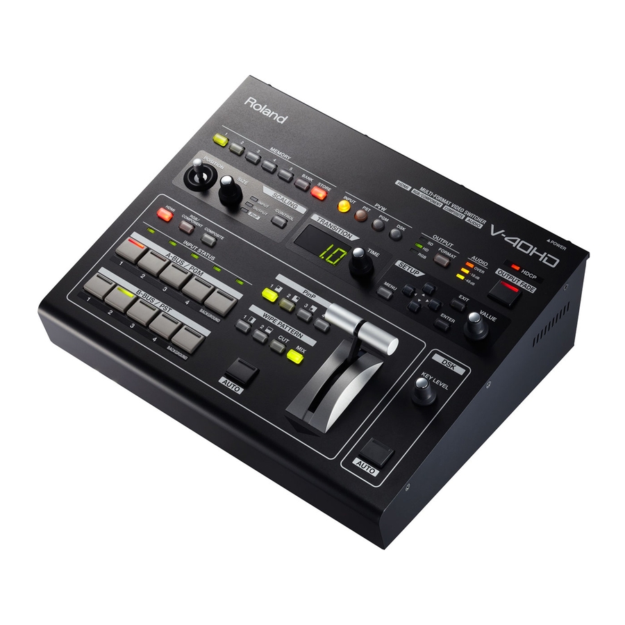
Page 14: Part Names And Functions
It flashes when no output device is connected or when the connected device is not compatible with HDCP. Unlighted It goes dark when the V-40HD’s HDCP-signal input/output mode is off. 6. OUTPUT FADE Button This applies fade to final output. The button flashes while the fade is in progress. The button lights up continuously when a fade- out has been completed. - Page 15 [TRANSITION] dial. 14. SETUP Section Use this when displaying the menu screen to change settings on the V-40HD (p. 45). 15. DSK Section When performing DSK composition, pressing the [AUTO] button in this section to make the DSK source (foreground video) appear or disappear.
-
Page 16: Rear Panel
This is for connecting a USB memory device for copying data saved in internal memory. * Never eject or insert a USB memory device while the V-40HD is powered up. Doing so might cause loss of data in the V-40HD or on the USB memory device. -
Page 17: Connecting External Equipment
* To prevent malfunction and equipment failure, always turn down the volume, and turn off all the units before making any connections. fig.peripheral-connection.eps For information on signal formats that can be input and output, refer to “About Input/Output Formats” (p. 24). Signal Flow The internal signal flow of the V-40HD is as shown below. Video Signals fig.signal-flow.eps INPUT 1... - Page 18 Connecting External Equipment Audio Signals fig.audio-signal-flow.eps INPUT 1 INPUT 2 INPUT 3 INPUT 4 Audio Input RGB/ RGB/ RGB/ RGB/ Component Component Component Component HDMI Composite HDMI Composite HDMI Composite HDMI Composite Ch1.HDMI Ch2.HDMI Ch3.HDMI Ch4.HDMI Audio In Audio Volume Audio Volume Audio Volume Audio Volume...
-
Page 19: Connecting Source Equipment
Connect video cameras or other devices capable of HDMI output to the HDMI connectors at INPUT 1 through 4. fig.HDMI-connection.eps To assign HDMI input to channel 1, go to [A-BUS/PGM] and press [1], then press the [HDMI] button. When the V-40HD detects the HDMI input, the [INPUT STATUS] indicator of the channel 1 lights up. - Page 20 * When connecting equipment that has an RCA type output jack, use the included RCA - BNC conversion plug. fig.composite-connection.eps To assign composite input to channel 3, go to [A-BUS/PGM] and press [3], then press the [COMPOSITE] button. When the V-40HD detects the composite input, the [INPUT STATUS] indicator of the channel 3 lights up.
-
Page 21: Connecting Audio Sources
Connect audio mixers or other audio sources to the AUDIO INPUT connectors. Input made via these connectors is output from HDMI connectors in the OUTPUT 1/2 sections together with the results of video mixing on the V-40HD. * When connection cables with resistors are used, the volume level of equipment connected to the inputs (AUDIO INPUT) may be low. If this happens, use connection cables that do not contain resistors. -
Page 22: Connecting Output Equipment
Connecting External Equipment Connecting Output Equipment For information on the signal formats that can be output from the V-40HD, refer to “About Input/Output Formats” (p. 24). Connecting a Projector or Recording Unit Make the connection to the connector in OUTPUT 1 or 2 sections. -
Page 23: Connecting Tally-Capable Equipment
Connecting Tally-capable Equipment The V-40HD is equipped with a D-Sub 15-pin TALLY connector. Connecting a video monitor capable of tally input to this makes it possible to illuminate the tally lamps on the monitor. The lamp is switched on and off according to the channel selection, enabling you to see which channel is currently in use on the monitor. -
Page 24: About Input/Output Formats
About Input/Output Formats Input Formats It is possible to input signal of various formats to INPUT 1-4 of the V-40HD. Signals of the following formats can be input. The input format is detected automatically. Frame Rate 59.94 Hz 50 Hz... -
Page 25: Using The Buttons To Change The Output Format For Output 1/2
1024 x 768/60 Hz 1024 x 768/75 Hz Output Formats from the Connectors Signals in the following formats can be output from the respective output connectors on the V-40HD. Refer to Output Menu (p. 46). OUTPUT 1/2 Frame Rate 59.94 Hz... -
Page 26: Inputting Hdcp Signals
Inputting HDCP Signals By default, the HDCP (High-bandwidth Digital Content Protection) setting of the V-40HD is turned off. This means that HDCP- applied signals from Blu-ray Disc players and the like cannot be input. When inputting signals to which HDCP is applied, follow the procedure shown below to change the setting. - Page 27 Inputting HDCP Signals About the HDCP Indicator The [HDCP] indicator on the top panel operates as described below. Lighted Turn on the HDCP setting and HDCP-compatible device(s) is connected to any of the HDMI connectors of OUTPUT 1/2 or PVW OUT. Turn on the HDCP setting but no device is connected to any of the HDMI connectors of OUTPUT 1/2 or PVW OUT.
-
Page 28: Basic Operations
Using this unit makes it possible to create video transitions that occur at extremely high speeds. Depending on physical condition, viewing such video might cause headache or discomfort. Never use this unit to create or present such video that might be distressful to health. Roland assumes no responsibility in the event of any distress experienced by you or other viewers. - Page 29 Basic Operations 2. Select a transition effect. Use the [WIPE PATTERN] buttons to select the transition effect you want to apply. * Using the [CUT] button makes the video change instantly, with no transition effect applied. fig.transition-select.eps Start Finish Video sources wipe from one to the other during the switch process.
-
Page 30: Switching The Video Using The Video Fader
Basic Operations Switching the Video Directly It is also possible to directly switch the video pressing the buttons in [A-BUS/PGM] section. However, a short black image is inserted between 2 video images on the conditions below. • When a direct switching operation is carried out while a logo/text is composited using the DSK function (p. 35). • [DSK] is selected as the dislay mode of preview monitor and [PST] is selected as the output source for OUTPUT 1/2. -
Page 31: Switching In The A/B Mode
Basic Operations Switching in the A/B Mode Changing the Operation Mode For information on using the menus, also refer to “Menu Operations and Menu List” (p. 45). 1. Display the System menu. Press the [MENU] button to display the menu. Use the [CURSOR] buttons to select [System], then press the [ENTER] button to display the System menu. -
Page 32: Switching In The A/B Mode
Basic Operations Switching in the A/B Mode 1. Select the A-Bus and B-Bus video. Select the channels for A-Bus and B-Bus. Selecting a channel makes the button indicator light up red or green. fig.select-AB-channel.eps 2. Select a transition effect. Use the [WIPE PATTERN] buttons to select the transition effect you want to apply. 3. -
Page 33: Applying Fade To Final Output
Basic Operations Applying Fade to Final Output Use the [OUTPUT FADE] button to apply a fade to the final output of the V-40HD. Applying a fade makes the output video gradually disappear (fade-out) or appear (fade-in). fig.fade-button.eps 1. Apply a fade-out. -
Page 34: Compositing The Video
Compositing the Video Compositing Using Picture-in-Picture This composites an inset screen into background video. Here below is the procedure to composite in PGM/PST mode. fig.PinP-image.eps Inset Screen Picture in Picture Background 1. Select the background channel. Use the buttons (1 through 4) in the [A-BUS/PGM] section to select the background channel. * If you want to use a plain colored background, select [BACKGROUND] in the [A-BUS/PGM] section. -
Page 35: Compositing Using Dsk
Compositing the Video 4. Adjust the size and position. At the SCALING section, press the [CONTROL] button to make the [PinP] indicator light up. Use the [POSITION] joystick and the [SIZE] dial to adjust the display position and size of the inset screen. fig.adjust-size-position.eps 5. - Page 36 Compositing the Video 2. Set the preview monitor to DSK mode. Select the [DSK] in PVW selector to preview the DSK composition. 3. Adjust the amount of keying. At the DSK section, turn the [KEY LEVEL] dial to adjust the amount of keying. Check the amount on the preview monitor. fig.DSK-level.eps 4.
-
Page 37: Audio-Related Features
Audio-related Features Selecting an Audio Source You can select the source for the audio to output via HDMI connectors in OUTPUT 1/2. At the Audio menu (p. 49), select one from below in [HDMI Output]. Ch1. HDMI Audio Only HDMI audio channel 1 is output. Ch2. -
Page 38: Aligning The Timing Of Video And Audio (Lip-Sync)
Audio-related Features Aligning the Timing of Video and Audio (Lip-sync) You can use the steps below to apply delay to audio output to align it with the timing of the video. 1. Display the Audio menu. Press the [MENU] button to display the menu. Use the [CURSOR] buttons to select [Audio], then press the [ENTER] button to display the Audio menu. -
Page 39: About Other Features
About Other Features Enlarging/Reducing the Picture Using the [SIZE] dial in the SCALING section, you can enlarge or reduce the view of the picture. You can also use the [POSITION] joystick to change the display position. * You can enlarge or reduce the picture within a range of 10% to 1,000%. Enlarging/Reducing the Source Picture 1. -
Page 40: Saving/Recalling Settings
Recalling Saved Settings When the V-40HD starts up, the settings saved at memory number 1 in bank 1 are loaded. To recall saved settings, first press a [BANK] button to select the bank. Pressing the button for a memory number then puts the panel in the saved state. -
Page 41: Using A Usb Memory Device
* Formatting permanently deletes all data saved on the USB memory device. 5. Exit the menu. Press the [EXIT] button several times to quit the menu. Note that USB memory devices not formatted on the V-40HD cannot be recognized. - Page 42 About Other Features Copying Settings to a USB Memory Device You can copy data saved in the internal memory to a formatted USB memory device. A batch copy of all data in internal memory from 1-1 to 5-5 and the unit’s common setting is carried out at this time. 1.
-
Page 43: Changing The Preview Labels
About Other Features Changing the Preview Labels You can change the text for channel names displayed on the preview monitor. Up to 8 characters of text can be displayed. 1. Display the System menu. Press the [MENU] button to display the menu. Use the [CURSOR] buttons to select [System], then press the [ENTER] button to display the System menu. -
Page 44: Returning To The Factory-Default State
About Other Features Returning to the Factory-default State This returns various settings to their factory defaults. If following the instructions for a procedure results in operation that differs from what is described in the Owner’s Manual, execute a factory reset. * Executing a factory reset causes all setting values saved up to then to be lost. -
Page 45: Menu Operations And Menu List
Menu Operations and Menu List Menu Operations To make various settings for the V-40HD, use the menu screens displayed on the preview monitor. Menu operations are described below. * For information on the menu items, refer to the following pages. -
Page 46: Menu List
Menu Operations and Menu List Menu List Display and setting values shown enclosed in square brackets (“[ ]”) are factory-default values. You can return a setting value to its factory default by holding down the [ENTER] button and pressing the [EXIT] button. Input menu No Signal, 720x480@59.94 Hz - 1920x1200@60.00 Hz This part displays the format of the current input signal. -
Page 47: Output Menu
Menu Operations and Menu List * You can adjust the values of below items only while you are selecting RGB/Component as the source. Sampling Use the following items to make settings related to sampling. Auto Sampling Execute Press [ENTER] to execute the auto sampling. Position H -1920 –... -
Page 48: Transition Menu
Menu Operations and Menu List Detailed setup for Composite Zoom 50% - [100%] This sets the zoom ratio. This selects the cropping format. For details of the values, Type [Full], Letterbox, Crop, Dot by Dot, Manual see [Type] of [Scaling] in the Input menu (p. 46) Size H -1000 - [0] - +1920 This sets the horizontal size. -
Page 49: Audio Menu
Menu Operations and Menu List DSK menu PGM Output [OFF],ON This turns final output of DSK on/off. This selects the way of appearance/disappearance of foreground Transition CUT, [MIX] image. Luminance 1 (White), [Luminance 2 (Black)], Type This select the type (extraction color) of DSK. Chroma 1 (Blue), Chroma 2 (Green) Level... -
Page 50: System Menu
The settings for items shown in gray in the table are not saved to MEMORY buttons (1-1 through 5-5). You cannot save multiple settings for these items using the MEMORY buttons. Only one setting per item can be saved to the V-40HD’s internal memory. Such settings are saved when you exit the menu. - Page 51 Menu Operations and Menu List Editing PVW labels Indicate OFF, [ON] This turns display of red/green borders and labels on/off. [“”PST””] Pressing [ENTER] displays the label entry screen during PST display. [“”PGM””] Pressing [ENTER] displays the label entry screen during PGM display. [“”DSK””] Pressing [ENTER] displays the label entry screen during DSK display.
-
Page 52: Appendices
Appendices Main Specifications Signal Processing Video 4 : 4 : 4 (Y/Pb/Pr), 10 bits * The output processing is 4:2:2, 8 bits. Audio processing Sampling rate : 24 bits/48 kHz, 2ch Input/Output Formats Refer to “About Input/Output Formats“ (p. 24). Input Jacks HDMI Type A (19 pins) x 4 (INPUT 1--4) -
Page 53: About Remote Control
MIDI VISUAL CONTROL fig.MVC-logo.eps The V-40HD can be operated remotely from a device that supports MIDI Visual Control. MIDI Visual Control is a feature that uses MIDI to link visual expression to a musical performance. About the Security Slot You can attach a commercially available security wire here to prevent theft. -
Page 54: Troubleshooting
Appendices Troubleshooting Nothing is displayed on the preview monitor. Does the connected monitor support a resolution and refresh rate of 1920 x 1080/60 Hz (progressive)? Nothing is displayed if the monitor is not compatible. Also, nothing is displayed if the monitor does not support HDCP signals. If you are making the connection using an HDMI-DVI conversion cable, go to the Output menu and select DVI-D in PVW Output. - Page 55 Adjust [HDMI Audio Delay] and [Audio In Delay] on the Audio menu. A USB memory device cannot be used. Was the USB memory device formatted on the V-40HD? A USB memory device that has not been formatted on this product cannot be used. Also, operation has been tested for commonly available USB memory devices, but operation of all USB memory devices is not assured.
-
Page 56: Index
Index A/B ........... 31, 32 Tally . - Page 57 Model Name : V-40HD Type of Equipment : Video Switcher Responsible Party : Roland Systems Group U.S. Address : 5100 S.Eastern Avenue, Los Angeles, CA 90040-2938, U.S.A. Telephone : (323) 890 3700...
Need help?
Do you have a question about the V-40HD and is the answer not in the manual?
Questions and answers