Advertisement
BS-657
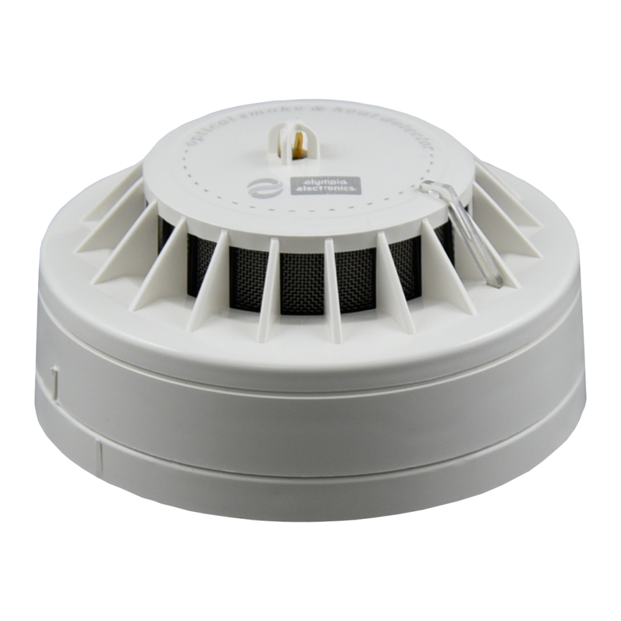
OPTICAL SMOKE AND THERMAL DETECTOR
TECHNICAL CHARACTERISTICS
OPERATION VOLTAGE
START UP POWER CONSUMPTION
STAND BY POWER CONSUMPTION
ALARM POWER CONSUMPTION
SENSITIVITY
INDICATORS
CLASS
OUTPUT
DEGREES OF COVER PROTECTION
PRODUCED IN ACCORDANCE WITH
OPERATION TEMPERATURE RANGE
RELATIVE HUMIDITY
EXTERNAL DIMENSIONS
TYPICAL WEIGHT
GUARANTEE
GENERAL
Before installing the detector, the user must
read these instructions carefully and store this
manual for future reference. The BS-657 is
optical smoke and thermal detector.
The detectors BS-657 were created to offer
quick detection in case of fire.
They have two parts, one plastic base which is
installed on the ceiling and the main unit of the
detector which is fastened to the base by a
simple turning to the right. The detectors have
an indication led which lights continuously in
case of fire detection until there is a reset
signal from the panel. The indication led also
flashes every 4 sec to indicate good operation.
These detectors can cooperate with
conventional fire alarm panels like BS-632 and
BS-636.
OPERATION CHECK
To test the optical detector you can spray a
small amount of smoke into the detector's
chamber. You can use the special smoke
device A-752 of our company, or a similar
device. To check the thermal limit you need a
special tool.
It is advised to conduct a good operation test
every 6 months and every time the detector
position is changed.
It is essential to have good air circulation inside
the detector. Therefore care must be taken so
that the vents of the detector are not covered.
NOTE
The detectors must be placed in the ceiling on
Page 1 from 2
18-30V DC
150μA for 50 sec
50μA
20-30mA
0.120dB/m and 58-62°C
Alarm LED
A2R
To panel / to external LED driver (BS-572)
IP20
EN 54-5, EN 54-7
o
-10 to 60 C
Up to 95%
103 (diam.) x 48 (height) mm
160gr.
2 years
visible areas with no side obstacles and away
from sides with no air circulation or strong air
currents and vapors. Each detector covers
2
almost 50 m and the distance between two
detectors must not exceed 15m. Also the
detectors must be placed away from
fluorescent tubes at least 50 cm.
The cables cross section must be from 0.5 to
2
1.5mm .
ATTENTION!!
After the device is installed, care must be taken,
so that the detector vents are not blocked by
anything (i.e. dust, paint). Failing to do so will
prevent the smoke particles to enter the
detection chamber.
After the installation, it is the sole
responsibility of the user to maintain the
detector for good operation.
Certification
The Rate of rise heat detetor BS-657 is
certified from H.E.E.Q.A.C. Also
H.E.E.Q.A.C. controls the production
under CPR number:
BS-657
RATE OF RISE HEAT
DETECTOR
0848-CPR-017
15
EN-54-5: 2000 + A1: 2002
EN-54-7: 2000 + A1: 2002 + A2: 2006
KOLINDROS PIERIAS
60061 GREECE
921657000_09_002
From zone
of the panel
Connection
You can connect up to 30 detectors BS-657 on each zone.
If the power of the detectors is turned off, wait for 3-5 seconds before you turn the power on again.
1. Detach the detector from it's base by turning it anticlockwise until the side marks are aligned.
2. Install the base with the included mounting parts (point 5).
3. Connect the power cables (respect to polarity) according to the installation requirements (figure
1,2).
4. Place carefully the detector, so as to align the side marks and turn it clockwise all the way.
Power the device and after 3-5 seconds will be ready to operate.
CONNECTION
1. IN-OUT -L : It is connected to the zone of the panel or to the (IN-OUT -L) contact of the
previous detector.
2. OUT +R : It is connected to the next detector (IN +L) or if it is the last one to the terminal resistor.
3. OUT +R and -R : It is connected with BS-572.
4. IN +L : It is connected to the zone of the panel or to the (OUT +R) contact of the previous
detector.
Olympia Electronics guarantees the quality, condition and operation of the goods. The period of warranty
is specified in the official catalogue of Olympia Electronics and also in the technical leaflet, which
accompanies each product. This warranty ceases to exist if the buyer does not follow the technical
instructions included in official documents given by Olympia Electronics or if the buyer modifies the goods
provided or has any repairs or re-setting done by a third party, unless Olympia Electronics has fully
agreed to them in writing. Products that have been damaged can be returned to the premises of our
company for repair or replacement, as long as the warranty period is valid.
Olympia Electronics reserves the right to repair or to replace the returned goods and to or not charge the
0848
buyer depending on the reason of defection. Olympia Electronics reserves the right to charge or not the
buyer the transportation cost.
HEAD OFFICE
72nd km. O.N.R. Thessaloniki-Katerini
P.C. 60300 P.O. Box 06 Εginio Pierias Greece
www.olympia-electronics.gr
info@olympia-electronics.gr
Page 2 from 2
Installation procedure
1
2
Indication marks
Indication
LED
Figure 1.
Warranty
Warranty
Connection
with external
Mounting base
LED BS-572
+
5
5
R
Figure 2
921657000_09_002
Advertisement
Table of Contents

Related Manuals for olympia electronics BS-657


Summary of Contents for olympia electronics BS-657
- Page 1 6 months and every time the detector DETECTOR Olympia Electronics reserves the right to repair or to replace the returned goods and to or not charge the 0848 position is changed.
- Page 2 6 months and every time the detector DETECTOR Olympia Electronics reserves the right to repair or to replace the returned goods and to or not charge the 0848 position is changed.
Need help?
Do you have a question about the BS-657 and is the answer not in the manual?
Questions and answers