Moxa Technologies CN2510 Series User Manual
Async server
Hide thumbs
Also See for CN2510 Series:
- Quick installation manual (2 pages) ,
- Quick installation manual (8 pages) ,
- Quick installation manual (2 pages)
Table of Contents
Advertisement
Quick Links
Advertisement
Table of Contents

Related Manuals for Moxa Technologies CN2510 Series


Summary of Contents for Moxa Technologies CN2510 Series
- Page 1 CN2510 Async Server User’s Manual www.moxa.com/product First Edition, May 2004...
- Page 2 Information provided in this manual is intended to be accurate and reliable. However, Moxa Technologies assumes no responsibility for its use, or for any infringements on the rights of third parties that may result from its use.
-
Page 4: Table Of Contents
Table of Contents Introduction ..................1-1 Chapter 1 Product Features..........1-2 Hardware....................1-2 Software....................1-2 Package Checklist..........1-2 Front Panel..........1-3 Rear Panel........... 1-3 Bottom Label..........1-3 Getting Started .................2-1 Chapter 2 Hardware Installation........2-2 Desktop ..................... 2-2 Rackmount....................2-2 Wiring Requirements ................2-2 Connecting CN2510-8/16’s Power ............ - Page 5 RAW Mode....................5-6 Configuring Port Setting – Port Menu [Line] ....5-7 Save............5-9 Restart............5-9 ASPP Library Introduction ........5-10 ASPP Examples for Unix ........5-10 ASPP Examples for Windows ........5-11 Setting up UDP Communication.............6-1 Chapter 6 Configuring Port Operation Mode – Port Menu [Mode] ... 6-2 Raw UDP Mode..................
- Page 6 Setting up Unix Hosts........11-9 Setting up a SCO Unix Host ..............11-9 Setting up a SOLARIS X86 Host ............11-11 Setting up a LINUX Host ..............11-12 Setting up Windows Hosts ........11-13 Setting up a Windows NT Host ............11-13 Setting up a Windows 2000 Host............
- Page 7 Setting up UNIX Hosts........B-5 Installing the RADIUS Execution File .............B-5 RADIUS Server Configuration..............B-6 Basic/Extended Permission Group Setting ..........B-7 Setting up Windows NT Hosts ......... B-10 Setting up Windows 2000 Hosts ....... B-12 Setting up Windows 2003 Hosts ....... B-15 Pin Assignments..........
-
Page 9: Introduction
Introduction Chapter 1 Welcome to Moxa CN2510 Async Server, a communication server with 4/8/16 asynchronous RS-232 ports and one 10/100 Mbps Ethernet LAN port. CN2510 Async Server can be used to connect terminals, modems, printers, and other asynchronous serial devices to LAN hosts. CN2510 complies with TCP/IP and IEEE 802.3 specifications using standard Ethernet 10/100BaseT and twisted pair 10/100BaseTX cable as the physical medium. -
Page 10: Product Features
Product Features Hardware 1 LAN ports (Ethernet auto-detection 10/100 Mbps) Surge protection for each serial port 4 MB RAM, 2 MB Flash ROM Tx/Rx LED for each serial port System Status LEDs 8 or 16 RJ45 RS-232 serial ports, with up to 230.4 Kbps speed Software ASCII/Binary terminal modes with max. -
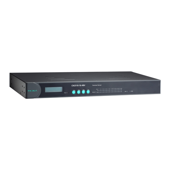
Page 11: Front Panel
Introduction Front Panel LCM Display Push Buttons LED Indicators Reset Button Color Description Reset None If you forget the password, press this button for 5 seconds, then the password will be removed. Ready Displays CN2510 system is powered on Ready Green Displays CN2510 system is ready Serial Tx... -
Page 13: Getting Started
Getting Started Chapter 2 This chapter includes instructions on where and how to install CN2510 Async Server, and discusses both basic and advanced software configuration. The following topics are covered: Hardware Installation Desktop Rackmount Wiring Requirements Connecting CN2510-8/16’s Power Connecting CN2510-8/16-48V’s Power Grounding CN2510-8/16-48V Connecting to the Network Connecting to a Serial Device... -
Page 14: Hardware Installation
Hardware Installation Desktop Place your CN2510 on a clean, flat, well-ventilated desktop. For better ventilation, attach the 4 pads from the desktop kit to the bottom of the unit, and leave some space between the CN2510 and other equipment. Do not place equipment or objects on top of the unit, as this might damage the server. -
Page 15: Connecting Cn2510-8/16'S Power
Getting Started Connecting CN2510-8/16’s Power Connect CN2510 100-240 VAC power line with its AC connector. If the power is properly supplied, the “Ready” LED will show a solid red color until the system is ready, at which time the “Ready” LED will change to a green color. Connecting CN2510-8/16-48V’s Power To connect CN2510-8/16-48V’s power cord with its terminal block, follow the steps given below: 1. -
Page 16: Connecting To The Console Port
Connecting to the Console Port A console is a combination of keyboard and monitor, and is used to configure settings and to monitor the status of your system. If you do not have a network environment, use a terminal, a PC running UNIX, or a PC with terminal emulation software (e.g., HyperTerminal in Windows;... - Page 17 Getting Started 1. Run upgrade.exe, located on the CN2510 CD. \Software\Firmware\upgrade.exe 2. CN2510 Utility starts searching for all CN2510s on the network. 3. CN2510 Utility lists all available servers on the network. Note that servers in gray are password protected. Double click the server in black, or click on from the menu bar to see the server settings.
-
Page 18: Run A Telnet Program
5. If you can’t find the server in the list, double-check the server’s power and network connections, and then use search to try locating the server again. Run a Telnet Program 1. Telnet over the network to the server’s IP address. Choose ansi/vt100 and press Enter 2. -
Page 19: Entering Console Via Console Terminal
Getting Started Entering Console via Console Terminal If you do not know the CN2510’s IP address, or it is not possible to use Telnet, you can instead use a direct console connection to enter the CN2510 console. First find a terminal emulation program for the console PC, such as HyperTerminal, which provides terminal emulation programs for Windows. - Page 20 2. Click on Next to Continue. 3. Select a directory in which to install CN2510 Utility and click on Next to accept. Then click on Next again to confirm and start. 4. When the installation is complete, run Start Programs PComm Terminal Emulator. 5.
- Page 21 Getting Started 6. In Communication Parameter, select COM2 for console connection, 115200 for Baud Rate, 8 for Data Bits, None for Parity, and 1 for Stop Bits. 7. In Terminal, select VT100 for terminal type. Press Enter to confirm. 8. Type 1 to select ansi/VT100 terminal type, and press Enter to enter MAIN MENU. CN2510 User’s Manual...
-
Page 22: Basic Server Configuration
9. You may use Edit Font to choose a different font display for MAIN MENU. 10. After entering CN2510’s MAIN MENU, use the following keys to move and select. Familiarize yourself with these cursor movement functions before we start the configuration process. -
Page 23: Basic Server Configuration Ii
Getting Started Async server name-This field contains the name of this CN2510. CN2510 uses this name to identify itself when requested by an SNMP station or UNIX host. The name should be an ASCII string with length no more than 40 characters. Spaces are allowed. Async server location-This field contains the location of this CN2510. -
Page 24: Advanced Server Configuration
2. In SERVER MENU, select Lan, and then press Enter. 3. In Lan, you must change the IP address, netmask, and any other information on your checklist (use the arrow keys to move the cursor). Press Esc to return to SERVER MENU. Ethernet LAN port 1: DHCP (client)-to enable or disable DHCP function. - Page 25 Getting Started RADIUS server IP-This field contains the IP address of the RADIUS server. RADIUS is short for Remote Authentication Dial-In User Service, and is used to authenticate remote dial-in users connecting from any ISP (Internet Service Provider). Skip this field if you do not have a RADIUS server on your network.
- Page 26 SIO data transfer timeout-This field defines the time CN2510 waits to send serial data to the Ethernet. The unit is milliseconds. Decreasing the timeout setting increases the efficiency. Host Table The Host_table is used to edit frequently referred to host names and their corresponding IP addresses.
-
Page 27: Save
Getting Started User Table The User_table is used for local authentication in dial-in/out access. The CN2510 User Table, which holds information for up to 64 users, can be used if you do not have an external RADIUS server for authentication. Save 1. -
Page 28: Restart
Restart 1. In MAIN MENU, select Restart. 2. Select System and then press Enter to continue. 3. The system will restart and the Telnet/Console session will terminate. 2-16 CN2510 User’s Manual... -
Page 29: Knowing Your Application
Knowing Your Application Chapter 3 This chapter discusses a variety of applications for CN2510 Async Server. Refer to the following diagrams to see which application matches your own. Determining your application will help you save time configuring both the hardware and software. CN2510 is a Async Server that can multitask, supporting various operation modes for different serial ports. -
Page 30: Windows Real Com (Nt Real Com Mode)
Windows Real COM (NT Real COM mode) Moxa offers the COM port driver for the whole series of Windows to control Moxa CN2510 Async Server’s serial ports. Through CN2510 Async Server, many applications which implemented serial boards can be enhanced to an Ethernet environment without modifying the software they are using right now. -
Page 31: Device Control (Aspp, Raw Mode)
Knowing Your Application Device Control (ASPP, RAW mode) For Device Control application, users can use standard Linux/Unix Socket programming in Linux/Unix or WinSock programming in the Windows environment to directly control devices’ data transmission. In this application, users use the standard Socket programming to communicate with the CN2510, and the operation mode used is TCP RAW mode, focusing only on data transmission without serial port control or serial modem signals control. -
Page 32: Console Management (Rtelnet Mode)
Console Management (Rtelnet mode) Console management is commonly used upon Console/AUX or COM port of routers, switches, and UPS. Rtelnet works the same as RAW mode that they only listen to one specific TCP port after booting up, and wait for the host on the network to initiate the connection. The difference is that the RAW mode does not provide conversion function of telnet protocol. -
Page 33: Multi-Host Tty (Fix Tty Mode)
Knowing Your Application Multi-host TTY (Fix TTY mode) When terminals need to communicate with multiple Unix hosts on the network via several simultaneous sessions, Multi-host TTY is the ideal method for transmission. When the communication starts, the Unix server on the network have to enable Moxattyd first to activate TTY port’s mapping function. -
Page 34: Network Printer (Raw/Lpd Mode)
Network Printer (RAW/LPD mode) CN2510 Async Server’s printing program (running under UNIX) provides an excellent solution for banking or stock exchange services with huge printing demands. Users can use Windows or Unix host’s network printer function via RAW mode. All you have to do is assign a specific IP address and a TCP port number to specify the printer’s location. -
Page 35: Setting Up Windows Real Com/Linux Real Tty/Unix Fixed Tty.4-1
Setting up Windows Real COM/Linux Chapter 4 Real TTY/Unix Fixed TTY CN2510 Async Server supports Real COM/TTY driver for Windows and Linux, allowing serial ports to be recognized as Real COM ports by the Windows operating system, or Real TTY ports by Linux environments. -
Page 36: Configuring Port Operation Mode - Port Menu [Mode]
Configuring Port Operation Mode – Port Menu [Mode] Open Port Menu Mode to install NT Real COM mode. 1. To enter CN2510 MAIN MENU, use either Telnet from a network terminal, or connect directly to CN2510 Async Server with a console terminal. Select ansi/vt100, and then press Enter. - Page 37 Setting up Windows Real COM/Linux Real TTY/Unix Fixed TTY 3. In MAIN MENU, use the arrow keys to select Port, and then press Enter. 4. In PORT MENU, select Mode, and then press Enter. 5. In Mode, use the arrow keys to move the cursor to the application corresponding to serial ports.
-
Page 38: Nt Real Com Mode
7. Repeat Step 6 to configure port settings. For example, you can follow the steps described below to configure Port 1 to Port 8 for NT Real COM mode application. NT Real COM Mode 1. Move the cursor to Description/more setting, press Enter, and a message window will open next. -
Page 39: Configuring Port Connection Setting - Port Menu [Line]
Setting up Windows Real COM/Linux Real TTY/Unix Fixed TTY Configuring Port Connection Setting – Port Menu [Line] 1. In MAIN MENU, use the arrow keys to select Port, and then press Enter. 2. In PORT MENU, select Mode, and then press Enter. 3. -
Page 40: Setting Up Hosts
Setting up Hosts Setting up Windows XP/2003 Hosts After using CN2510 Console Utility to set up a Windows XP/2003 host, you’ll need to install port driver on every Windows XP/2003 host needing access to CN2510 ports. Here we use Windows XP as an example for illustrating installation. - Page 41 Setting up Windows Real COM/Linux Real TTY/Unix Fixed TTY 3. The next window to open will ask you if the hardware is connected. Select Yes, I have already connected the hardware, and click on Next to continue. 4. Select Add a new hardware device in the next window that opens. And then click on Next to continue.
- Page 42 5. In the window that opens next, select Install the hardware that I manually select from a list (Advanced) to install the hardware. And then click on Next to continue. 6. The window that opens next will ask you select the type of hardware you are installing. Select Multi-port serial adapters, and click on Next to continue.
- Page 43 Setting up Windows Real COM/Linux Real TTY/Unix Fixed TTY 7. The window that opens next will ask you to select the device driver you want to intall for this hardware. Select Have Disk to install from a disk, select the driver file NPSERVER.INF, and locate the driver file.
- Page 44 8. In the next window to open, select your CN2510 model, and click on Next to continue. 9. The Wizard will start installing the Server driver, and automatically search for CN2510 products over the network. 10. Although the next window to open states that software hasn’t passed Windows Logo testing, you can rest assured that this driver has already been tested and been shown that it can support this Windows OS.
- Page 45 Setting up Windows Real COM/Linux Real TTY/Unix Fixed TTY 11. You can either select the CN2510 that has been located, or select Manually Enter the IP address of NPort Server / Async Server to search for CN2510. Click on Next to finish installing CN2510.
- Page 46 Installing Ports 1. After CN2510 server installation is finished, Windows will automatically pop out another window stating that a new hardware is found. Select Install from a list or specific location (Advanced), and click on Next to continue. 4-12 CN2510 User’s Manual...
- Page 47 Setting up Windows Real COM/Linux Real TTY/Unix Fixed TTY 2. The window that opens next will ask you to choose your search and installation options. Select Include this location in the search, and click on Next to continue. 3. The system will install all necessary files automatically. CN2510 User’s Manual 4-13...
- Page 48 4. Although the next window to open states that software hasn’t passed Windows Logo testing, you can rest assured that this driver has already been tested and been shown that it can support this Windows OS. Click on Continue Anyway to proceed. Then it will show the following window.
- Page 49 Setting up Windows Real COM/Linux Real TTY/Unix Fixed TTY Configuring CN2510 in a Windows XP/2003 Environment As soon as CN2510 driver is installed, the driver will guide you through CN2510’s configuration. Or you can configure CN2510 later after the driver is installed. Here we will introduce Real COM Mapping configuration.
- Page 50 2. Click on NPort Server/Async Server Status’s Settings to configure CN2510’s Basic Configuration, Password, and Access Control. 4-16 CN2510 User’s Manual...
- Page 51 Setting up Windows Real COM/Linux Real TTY/Unix Fixed TTY CN2510 User’s Manual 4-17...
- Page 52 4-18 CN2510 User’s Manual...
-
Page 53: Setting Up Windows 2000 Hosts
Setting up Windows Real COM/Linux Real TTY/Unix Fixed TTY 3. Click on Port Setting to configure COM port’s data transmission mode and FIFO. Setting up Windows 2000 Hosts After setting up a CN2510 Async Server via Control Panel in a Windows 2000 environment, you’ll need to install port driver on every Windows 2000 host needing access to CN2510 ports. - Page 54 3. In the next window to open, select Add/Troubleshoot a device, and click on Next to continue. In the next window to open, select No, I want to select the hardware from a list. 4-20 CN2510 User’s Manual...
- Page 55 Setting up Windows Real COM/Linux Real TTY/Unix Fixed TTY 4. In the window that opens next, select Multi-port serial adapters from the Hardware Type list. CN2510 User’s Manual 4-21...
- Page 56 5. Select Have Disk to install from a disk, select the driver file NPSERVER.INF, and locate the driver file. 6. In the next window to open, select your CN2510 model, and click on Next to continue. 4-22 CN2510 User’s Manual...
- Page 57 Setting up Windows Real COM/Linux Real TTY/Unix Fixed TTY 7. The Wizard will start installing the Server driver, and automatically search for CN2510 products over the network. 8. Although the next window to open states that software hasn’t passed Windows Logo testing, you can rest assured that this driver has already been tested and been shown that it can support this Windows OS.
- Page 58 4-24 CN2510 User’s Manual...
- Page 59 Setting up Windows Real COM/Linux Real TTY/Unix Fixed TTY Installing Ports 1. After CN2510 server installation is finished, Windows will automatically pop out another window stating that a new hardware is found. Click on Next to continue. 2. The window that opens next, select Search for a suitable driver for my device (recommended).
- Page 60 4. Click on Next to continue. 5. Moxa Port 0 installation is finished. The step 1 to step 4 will be repeated for several times, depending on how many serial ports on your CN2510 product. After the installation is complete, you can find the COM ports in Device Manager. 4-26 CN2510 User’s Manual...
- Page 61 Setting up Windows Real COM/Linux Real TTY/Unix Fixed TTY Configuring CN2510 in a Windows 2000 Environment As soon as CN2510 driver is installed, the driver will guide you through CN2510’s configuration. Or you can configure CN2510 later after the driver is installed. Here we will introduce Real COM Mapping configuration.
- Page 62 2. Click on NPort Server/Async Server Status’s Settings to configure CN2510’s Basic Configuration, Password, and Access Control. 4-28 CN2510 User’s Manual...
- Page 63 Setting up Windows Real COM/Linux Real TTY/Unix Fixed TTY CN2510 User’s Manual 4-29...
- Page 64 3. Click on Port Setting to configure COM port’s data transmission mode and FIFO. 4-30 CN2510 User’s Manual...
-
Page 65: Setting Up Windows 95/98/Me/Nt Hosts
Setting up Windows Real COM/Linux Real TTY/Unix Fixed TTY Setting up Windows 95/98/ME/NT Hosts CN2510 Async Server uses the same driver in Windows 95/98/ME environment, and another driver in Windows NT environment. The procedures for installation are the same. For this reason, you have to make sure you are installing the correct driver. - Page 66 2. Select Custom mode, and click on Next to continue. 4-32 CN2510 User’s Manual...
- Page 67 Setting up Windows Real COM/Linux Real TTY/Unix Fixed TTY 3. Click on Next to finish the installation. 4. After the driver is installed, Add Server Wizard will start to help you configure CN2510. As illustrated below, you can either choose to enter the IP address manually, or use auto search locate servers and select one from the server list.
- Page 68 5. In the window that opens next, Add Server Wizard will ask you to enter CN2510 LAN’s IP address. Click on Next to continue. 6. Select the corresponding COM Port. The system will automatically map all COM Ports. 4-34 CN2510 User’s Manual...
- Page 69 Setting up Windows Real COM/Linux Real TTY/Unix Fixed TTY 7. The next step is to set the password for this CN2510. Enter the password, and click on Next to continue. 8. Add Server Wizard will show the entire information about CN2510. CN2510 User’s Manual 4-35...
- Page 70 9. You have to save the data after you return to the main page. Click on the disk icon on the upper left corner to map CN2510’s serial ports to standard COM ports. Configuring CN2510 in a Windows 95/98/ME/NT Environment As soon as CN2510 driver is installed, the driver will guide you through CN2510’s configuration.
- Page 71 Setting up Windows Real COM/Linux Real TTY/Unix Fixed TTY 1. From Start/Properties/NPort Server, Click on NPort Server Manager. And click which CN2510 you want to setup. Right click it and select Server Properties like as follow. 2. In general page, you could see the Server Information here. It’s include Serial No., Server Name, Server IP, Netmask, and you also could select this CN2510 want to use DHCP to get a free IP address or fixed IP address.
- Page 72 4. In Access Control page, you could add or remove any IP address to allow it access CN2510 or not. 5. In advanced page, you could adding routes to CN2510. In general, CN2510 has a column to setup Default Gateway, so we think you could ignore this configuration. 4-38 CN2510 User’s Manual...
- Page 73 Setting up Windows Real COM/Linux Real TTY/Unix Fixed TTY CN2510 User’s Manual 4-39...
-
Page 75: Setting Up Device Control
Setting up Device Control Chapter 5 For Device Control application, users can use standard Linux/Unix Socket programming in Linux/Unix or WinSock programming in the Windows environment to directly control devices’ data transmission. In this application, users use the standard Socket programming to communicate with the CN2510, and the operation mode used is TCP RAW mode, focusing only on data transmission without serial port control or serial modem signals control. -
Page 76: Configuring Port Operation Mode - Port Menu [Mode]
Configuring Port Operation Mode – Port Menu [Mode] Open Port Menu Mode to install NT Real COM mode. 1. To enter CN2510 MAIN MENU, use either Telnet from a network terminal, or connect directly to CN2510 Async Server with a console terminal. Select ansi/vt100, and then press Enter. - Page 77 Setting up Device Control 3. In MAIN MENU, use the arrow keys to select Port, and then press Enter. 4. In PORT MENU, select Mode, and then press Enter. 5. In Mode, use the arrow keys to move the cursor to the application corresponding to serial ports.
-
Page 78: Aspp Mode
We already selected a application mode for each serial port. Now let’s talk about more details on Device Control: CN2510 Device Control’s ASPP/RAW mode. ASPP, which is developed by Moxa, provides an easy-to-use TCP/IP socket programming library and other useful functions. CN2510 RAW mode allows self-definition on applications via serial data transmitted/received over the Ethernet. - Page 79 Setting up Device Control 1. Move the cursor to the Mode column of the corresponding port, and then press Enter to see 2 modes for Device Control applications: ASPP and RAW. Please select ASPP Mode. 2. Move the cursor to the Description/more setting column, and then press Enter to open the setting window.
-
Page 80: Raw Mode
RAW Mode RAW mode is used for standard TCP/IP socket programs. RAW mode provides a transparent communication link between the network socket program and the corresponding Async port. 1. Move the cursor to the Mode column of the corresponding port, and then press Enter to see two modes for async device control applications: ASPP and RAW. -
Page 81: Configuring Port Setting - Port Menu [Line]
Setting up Device Control addr exclusive port access. If left blank, all hosts on the network will have access to this port. Inactivity time 0-99 minutes Idle time setting for auto-disconnection Optional 0 min means no disconnection TCP alive check 0-99 minutes Specify the time slice for checking whether the Optional... - Page 82 Setting Value Notes Speed 50 bps to 230.4 Kbps Baud rate Bits 5/6/7/8 Data bits Stop Stop bits Parity None, Even, Odd, Mark, Space Parity Check FIFO Yes/No FIFO setting RTS/CTS Yes/No Hardware Flow Control XON/XOFF Yes/No Software Flow Control Discon.
-
Page 83: Save
Setting up Device Control Save 1. Press Y to save previous settings when exiting PORT MENU. 2. You may also save later. In MAIN MENU, select sAve to save all changed settings, and then press Enter to confirm. Restart 1. Return to MAIN MENU and select Restart. 2. -
Page 84: Aspp Library Introduction
3. The system will restart and the Telnet/Console session will terminate. Enter MAIN MENU again to check whether the settings have been changed. ASPP Library Introduction The CN2510 software CD contains example programs that illustrate how to successfully control the ASPP port. After uncompressing the file ASPP.tar.z, you will be able to find several basic subroutines in the \aspp\as.h folder. -
Page 85: Aspp Examples For Windows
Setting up Device Control 3. Create a socket for data port and connect to it. 4. Transfer data via data port. This example program continually sends the string “1234567890” to CN2510’s ASPP port and then reads back data when program ends. Setting: Target port: no parity, 8 data bits, 1 stop bit, software (XON/XOFF) flow control, no hardware (RTS/CTS). -
Page 87: Setting Up Udp Communication
Setting up UDP Communication Chapter 6 UDP is a non connection-oriented data transmission method. UDP has advantages of high speed and high data transmission efficiency, eliminating TCP’s handshaking process. But it comes with the price of sacrificing data integrity. UDP doesn’t have the functions of re-assembling and retransmitted packets like TCP when data is missing. -
Page 88: Configuring Port Operation Mode - Port Menu [Mode]
Configuring Port Operation Mode – Port Menu [Mode] Open Port Menu Mode to install NT Real COM mode. 1. To enter CN2510 MAIN MENU, use either Telnet from a network terminal, or connect directly to CN2510 Async Server with a console terminal. Select ansi/vt100, and then press Enter. - Page 89 Setting up UDP Communication 3. In MAIN MENU, use the arrow keys to select Port, and then press Enter. 4. In PORT MENU, select Mode, and then press Enter. 5. In Mode, use the arrow keys to move the cursor to the application corresponding to serial ports.
-
Page 90: Raw Udp Mode
Raw UDP Mode 1. Move the cursor to the Description/more setting column, and then press Enter to open the setting window. 2. UDP Description/more setting Window. Setting Value Notes Necessity Dest. IP The IP address range to UDP packets will be sent consecutively address 1 which the target data is from the first IP address to the last one. - Page 91 Setting up UDP Communication Src. IP IP address range The Legal IP addresses for receiving UDP Optional address permitted for receiving packets. As stated on the left column, 2/3/4 data from the network. there are UDP packets from 64 IP addresses in total will be received and sent e.g.
-
Page 92: Configuring Port Setting - Port Menu [Line]
Force Transmit timeout between characters and the total length of data must be smaller than or equal to CN2510’s internal buffer size. The serial communication buffer size of CN2510 is 1 K byte per port. 3. Repeat the steps above to set up all Raw UDP ports. 4. - Page 93 Setting up UDP Communication Setting Value Notes Speed 50 bps to 230.4 Kbps Baud rate Bits 5/6/7/8 Data bits Stop Stop bits Parity None, Even, Odd, Mark, Space Parity Check FIFO Yes/No FIFO setting RTS/CTS Yes/No Hardware Flow Control XON/XOFF Yes/No Software Flow Control Discon.
-
Page 94: Save
Save 3. Press Y to save previous settings when exiting PORT MENU. 4. You may also save later. In MAIN MENU, select sAve to save all changed settings, and then press Enter to confirm. Restart 1. Return to MAIN MENU and select Restart. 2. - Page 95 Setting up UDP Communication 3. The system will restart and the Telnet/Console session will terminate. Enter MAIN MENU again to check whether the settings have been changed. CN2510 User’s Manual...
-
Page 97: Setting Up Console Management
Setting up Console Management Chapter 7 This chapter includes information about how to set up CN2510 Async Server, allowing the terminal on the Ethernet to access CN2510’ serial ports. This chapter will introduce the APIs for the following functions: Configuring Port Operation Mode – Port Menu [Mode] RTelnet Mode Configuring Port Connection Setting –... -
Page 98: Configuring Port Operation Mode - Port Menu [Mode]
Configuring Port Operation Mode – Port Menu [Mode] Open Port Menu Mode to install NT Real COM mode. 1. To enter CN2510 MAIN MENU, use either Telnet from a network terminal, or connect directly to CN2510 Async Server with a console terminal. Select ansi/vt100, and then press Enter. - Page 99 Setting up Console Management 3. In MAIN MENU, use the arrow keys to select Port, and then press Enter. 4. In PORT MENU, select Mode, and then press Enter. 5. In Mode, use the arrow keys to move the cursor to the application corresponding to serial ports.
-
Page 100: Rtelnet Mode
CN2510 provides an RTELNET mode for the reverse terminal application. RTELNET mode allows Ethernet hosts to access serial hosts attached to CN2510’s serial ports, the reverse direction provided by CN2510’s terminal application. RTelnet Mode Reverse Telnet, or RTELNET, supports the Telnet program used by Ethernet hosts to login to serial hosts. -
Page 101: Configuring Port Setting - Port Menu [Line]
Setting up Console Management Setting Value Notes Necessity TCP port number Each of CN2510’s serial ports is mapped to a Optional TCP port. To avoid conflicts with TCP ports, set port numbers to 4001 for port1, 4002 for port2, etc. (like the default values). Source IP address IP address for Specify an IP address for this port for application Optional... - Page 102 3. Select the ports and configure the settings. Setting Value Notes Speed 50 bps to 230.4 Kbps Baud rate Bits 5/6/7/8 Data bits Stop Stop bits Parity None, Even, Odd, Mark, Space Parity Check FIFO Yes/No FIFO setting RTS/CTS Yes/No Hardware Flow Control XON/XOFF Yes/No...
-
Page 103: Save
Setting up Console Management Save 1. Press Y to save previous settings when exiting PORT MENU. 2. You may also save later. In MAIN MENU, select sAve to save all changed settings, and then press Enter to confirm. Restart 1. Return to MAIN MENU and select Restart. 2. - Page 104 3. The system will restart and the Telnet/Console session will terminate. Enter MAIN MENU again to check whether the settings have been changed. CN2510 User’s Manual...
-
Page 105: Setting Up Terminal Access
Setting up Terminal Access Chapter 8 We describe here the steps for configuring Moxa CN2510 as a Terminal Server. CN2510 provides Telnet and Rlogin protocols for terminals to establish connections with UNIX hosts. Two terminal modes are supported, ASCII terminal with up to 8 simultaneous sessions, and Binary terminal with one session for one user. -
Page 106: Configuring Port Operation Mode - Port Menu [Mode]
Configuring Port Operation Mode – Port Menu [Mode] Open Port Menu Mode to install NT Real COM mode. 1. To enter CN2510 MAIN MENU, use either Telnet from a network terminal, or connect directly to CN2510 Async Server with a console terminal. Select ansi/vt100, and then press Enter. - Page 107 Setting up Terminal Access 3. In MAIN MENU, use the arrow keys to select Port, and then press Enter. 4. In PORT MENU, select Mode, and then press Enter. 5. In Mode, use the arrow keys to move the cursor to the application corresponding to serial ports.
-
Page 108: Term_Asc Mode
TERM_ASC Mode After selecting the application mode for each serial port, we will discuss more detailed information on terminal settings. ASCII and Binary are 2 protocols used in Terminal Access. ASCII supports 8 terminal sessions, while Binary only supports 1 session. TERM_ASC supports 8 terminal sessions for each terminal. - Page 109 Setting up Terminal Access 4. TERM_ASC Description/More Setting window. Setting Value Notes Necessity Key Mapping Max. Sessions Configure the max. number of sessions Optional Change Session Hot key for change session Optional Quit Hot key for quit session Optional Erase-line Hot key for erase-line Optional Erase-character...
-
Page 110: Term_Bin Mode
prompt. Password prompt Password: Send Password information when receiving Optional this prompt Login user name ID information Optional Login password Password Password information Optional Terminal type Ansi Terminal type for outgoing connection Optional Inactivity time 0-99 minutes Idle time setting for auto-disconnection Optional 0 min means no disconnection Authentication type None/local/ser... - Page 111 Setting up Terminal Access 3. Move cursor to the Description/more setting column, and then press Enter to open the setting window. 4. TERM_BIN Description/More Setting window. Setting Value Notes Necessity Quit Key Defines the Quit key used to disconnect the Optional link between the current terminal session and the remote host.
-
Page 112: Configuring Port Setting - Port Menu [Line]
defined as "ogin:". Password prompt assword: Send Password information when receiving Optional this prompt. Since some prompts use "Password", others use "password", the prompt detection is defined as "assword:". Login user name ID information Optional Login password Password Password information Optional Terminal type Ansi... - Page 113 Setting up Terminal Access 3. Select the ports and configure the settings. Setting Value Notes Speed 50 bps to 230.4 Kbps Baud rate Bits 5/6/7/8 Data bits Stop Stop bits Parity None, Even, Odd, Mark, Space Parity Check FIFO Yes/No FIFO setting RTS/CTS Yes/No...
-
Page 114: Save
Save 1. Press Y to save previous settings when exiting PORT MENU. 2. You may also save later. In MAIN MENU, select sAve to save all changed settings, and then press Enter to confirm. Restart 1. Return to MAIN MENU and select Restart. 2. - Page 115 Setting up Terminal Access 3. The system will restart and the Telnet/Console session will terminate. Enter MAIN MENU again to check whether the settings have been changed. CN2510 User’s Manual 8-11...
-
Page 117: Setting Up Multi-Host Tty
Setting up Multi-host TTY Chapter 9 When terminals need to communicate with multiple Unix hosts on the network via several simultaneous sessions, Multi-host TTY is the ideal method for transmission. When the communication starts, the Unix server on the network has to activate Moxattyd first to TTY port’s mapping function. -
Page 118: Configuring Port Operation Mode - Port Menu [Mode]
Configuring Port Operation Mode – Port Menu [Mode] Open Port Menu Mode to install NT Real COM mode. 1. To enter CN2510 MAIN MENU, use either Telnet from a network terminal, or connect directly to CN2510 Async Server with a console terminal. Select ansi/vt100, and then press Enter. - Page 119 Setting up Multi-host TTY 3. In MAIN MENU, use the arrow keys to select Port, and then press Enter. 4. In PORT MENU, select Mode, and then press Enter. 5. In Mode, use the arrow keys to move the cursor to the application corresponding to serial ports.
-
Page 120: Fix Tty Mode
Fix TTY Mode 1. Move cursor to the Description/more setting column, and then press Enter to open the setting window. 2. Fix TTY Description/More Setting window. CN2510 User’s Manual... -
Page 121: Configuring Port Setting - Port Menu [Line]
Setting up Multi-host TTY Setting Value Notes Necessity Max. Sessions Configure how many connections for each Optional CN2510’s port. Terminal mode Star NT-560+ CN2510 provides 3 modes depending on the Optional connection mode supported by the terminal. NL-5000A VT100 Inactivity time 0-99 minutes Idle time setting for auto-disconnection. -
Page 122: Save
Setting Value Notes Speed 50 bps to 230.4 Kbps Baud rate Bits 5/6/7/8 Data bits Stop Stop bits Parity None, Even, Odd, Mark, Space Parity Check FIFO Yes/No FIFO setting RTS/CTS Yes/No Hardware Flow Control XON/XOFF Yes/No Software Flow Control Discon. -
Page 123: Restart
Setting up Multi-host TTY 2. You may also save later. In MAIN MENU, select sAve to save all changed settings, and then press Enter to confirm. Restart 1. Return to MAIN MENU and select Restart. 2. Select System, and then press Enter to continue. 3. - Page 124 1. Create a directory for Moxatty (e.g. /user/etc/moxatty) as shown below: #mkdir /usr/etc/moxatty #cd /usr/etc/moxatty 2. Extract code from the tar-formatted file moxatty.tar as follows: #tar xvf moxatty.tar 3. After the extraction is complete, locate the following files: program source code moxattyd.c configuration file moxattyd.cf...
-
Page 125: Moxatty For Different Applications
Setting up Multi-host TTY The option “–t 1” means the reconnection time is 1 minute after turning CN2510 on or off. NOTE Moxatty for Different Applications This section illustrates how to use MOXATTY with a number of different applications. Terminal Access To use terminal access the process getty must be activated while the system boots up. -
Page 126: Using Moxatty
Using Moxatty Starting MOXATTY Once you have completed the above settings, you can start. Follow the steps given below to ensure that MOXATTY is running correctly. See if the entries added to moxattyd.cf are correct. Run init q or reboot your system to start the MOXATTY daemon. If you see that moxattyd is running on your system, then MOXATTY has been successfully started. -
Page 127: Setting Up Dial-In/Out Of Band Management
Setting up Dial-in/out of Band Chapter 10 Management We describe here the steps required to configure Moxa CN2510 as a Dial-in/out Access Server. Dial-in Access allows remote users to access the LAN, whereas Dial-out Access allows LAN hosts to establish connections to other sites. The following topics are covered in this chapter: Configuring Port Operation Mode –... -
Page 128: Configuring Port Operation Mode - Port Menu [Mode]
Configuring Port Operation Mode – Port Menu [Mode] Open Port Menu Mode to install NT Real COM mode. 1. To enter CN2510 MAIN MENU, use either Telnet from a network terminal, or connect directly to CN2510 Async Server with a console terminal. Select ansi/vt100, and then press Enter. - Page 129 Setting up Dial-in/out of Band Management 3. In MAIN MENU, use the arrow keys to select Port, and then press Enter. 4. In PORT MENU, select Mode, and then press Enter. 5. In Mode, use the arrow keys to move the cursor to the application corresponding to serial ports.
-
Page 130: Pppd/Ppp Mode
PPPD/PPP Mode PPPD (PPP on demand) is used for dial-in services since it provides PPP services only when receiving a request from a remote PC. PPP provides standard PPP services for both dial-in and dial-out. 1. Move the cursor to the Mode column of the corresponding port, and then press Enter to see five mode options for dial-in/out applications. -
Page 131: Slipd/Slip Mode
Setting up Dial-in/out of Band Management Setting Value Notes Necessity Destination IP IP address for the DO assign an IP address for the remote addr remote Dial-in / user. Dial-out user Source IP address IP address for the CN2510 automatically assigns an IP Optional port address for the port. - Page 132 2. Select SLIPD for dial-in services only, or SLIP for both dial-in/out services. 3. Move the cursor to the Description/more setting column, and then press Enter to open the setting window. Setting Value Notes Necessity Destination IP IP address for the DO assign an IP address for the remote addr remote Dial-in /...
-
Page 133: Dynamic Mode
Setting up Dial-in/out of Band Management Dynamic Mode Dynamic mode integrates PPPD/SLIPD/Terminal dial-in services. Dynamic mode automatically detects which remote connection mode is being used, and provides corresponding services. You can further enable/disable PPP/SLIP/Terminal services by using Description/more setting. 1. Move the cursor to the Mode column of the corresponding port, and then press Enter to see five mode options for dial-in/out applications. - Page 134 SERVER MENU. You will need to set user’s information later in this chapter. Server: Check ID according to external RADIUS Server 5. Term parameters. Open the Detail-setting window to set more parameters (if necessary). Setting Value Notes Necessity Quit key Defines the Quit key used to disconnect the Optional link between the current terminal session and...
- Page 135 Setting up Dial-in/out of Band Management Terminal type ansi Terminal type for outgoing connection Optional Inactivity time 0-99 minutes Idle time setting for disconnection Optional 0 min means no disconnection TCP alive check 0-99 minutes Specify the time slice for checking whether Optional time the TCP connection is alive.
-
Page 136: Configuring Port Setting - Port Menu [Line]
Setting Value Notes Necessity Destination IP IP address for the DO assign an IP address for the remote addr remote Dial-in user user. Source IP address IP address for the CN2510 automatically assigns IP address Optional port for the port. Recommend: Blank IP netmask IP netmask... -
Page 137: Configuring Modem Initialization - Port Menu [Modem]
Setting up Dial-in/out of Band Management Setting Value Notes Speed 50 bps to 230.4 Kbps Baud rate Bits 5/6/7/8 Data bits Stop Stop bits Parity None, Even, Odd, Mark, Space Parity Check FIFO Yes/No FIFO setting RTS/CTS Yes/No Hardware Flow Control XON/XOFF Yes/No Software Flow Control... -
Page 138: Optional Welcome Message - Port Menu [Welcome_Msg]
3. Specify modem settings. Setting Value Notes Enable YES/NO Enable modem settings Initialize String Set modem initial string, for example, AT&S0 =1 is for auto-answer. Dial Up String Dial-up AT command Phone Number Number Set the number you use to dial out The Dial Up and Phone Number settings are only valid under PPP/SLIP mode. -
Page 139: Optional Local User Information - Server Menu [User_Table]
Setting up Dial-in/out of Band Management 3. Select YES to edit welcome message. 4. Press Esc to go back to PORT MENU. Optional local user information – Server Menu [User_table] In Server Menu [User_Table], set local user authentication information. If you set Incoming PAP check or Authentication type as Local instead of Server, you have to set [User_table] for user authentication. -
Page 140: Save
Save 1. Press Y to save previous settings when exiting PORT MENU. 2. You may also save later. In MAIN MENU, select sAve to save all changed settings, and then press Enter to confirm. Restart 1. Return to MAIN MENU and select Restart. 2. - Page 141 Setting up Dial-in/out of Band Management 3. The system will restart and the Telnet/Console session will terminate. Enter MAIN MENU again to check whether the settings have been changed. CN2510 User’s Manual 10-15...
- Page 142 10-16 CN2510 User’s Manual...
-
Page 143: Setting Up Network Printer
Setting up Network Printer Chapter 11 We describe here the steps for configuring Moxa CN2510 as a printer server. Up to 8/16 serial printers can be simultaneously connected to CN2510. The serial printer server function is configured through port menu, and is able to accommodate up to 16 ports. At the end of the chapter, the setting for one-port parallel printing is illustrated for both UNIX and Windows systems. -
Page 144: Configuring Port Operation Mode - Port Menu [Mode]
Configuring Port Operation Mode – Port Menu [Mode] Open Port Menu Mode to install NT Real COM mode. 1. To enter CN2510 MAIN MENU, use either Telnet from a network terminal, or connect directly to CN2510 Async Server with a console terminal. Select ansi/vt100, and then press Enter. - Page 145 Setting up Network Printer 3. In MAIN MENU, use the arrow keys to select Port, and then press Enter. 4. In PORT MENU, select Mode, and then press Enter. 5. In Mode, use the arrow keys to move the cursor to the application corresponding to serial ports.
-
Page 146: Raw Prn Mode
Raw PRN Mode 1. Move cursor to the Description/more setting column, and then press Enter to open the setting window. 2. Printer Description/More Setting window. Setting Value Notes Necessity Group Group 01-16 Group the printers so that printers in the same Optional group can share the printing load. -
Page 147: Lpd Prn Mode
Setting up Network Printer Group TCP port number Group TCP port number 2048 2056 2049 2057 2050 2058 2051 2059 2052 2060 2053 2061 2054 2062 2055 2063 3. Repeat the steps above to set all Fix TTY ports. 4. Press Esc to return to PORT MENU. LPD PRN Mode 1. -
Page 148: Configuring Port Setting - Port Menu [Line]
Setting Value Notes Necessity Queue name Letters Specify print queue’s name (in RAW mode) Fixed (RAW) Queue name Letters Specify print queue’s name (in ASCII mode) Fixed (ASCII) Append From Enable/Disable Specify paging Optional Feed TCP alive check 0-99 minutes Specify the time slice for checking whether the Optional time... - Page 149 Setting up Network Printer Setting Value Notes Speed 50 bps to 230.4 Kbps Baud rate Bits 5/6/7/8 Data bits Stop Stop bits Parity None, Even, Odd, Mark, Space Parity Check FIFO Yes/No FIFO setting RTS/CTS Yes/No Hardware Flow Control XON/XOFF Yes/No Software Flow Control Discon.
-
Page 150: Save
Save 1. Press Y to save previous settings when exiting PORT MENU. 2. You may also save later. In MAIN MENU, select sAve to save all changed settings, and then press Enter to confirm. Restart 1. Return to MAIN MENU and select Restart. 2. -
Page 151: Setting Up Unix Hosts
Setting up Network Printer 3. The system will restart and the Telnet/Console session will terminate. Enter MAIN MENU again to check whether the settings have been changed. Setting up Unix Hosts UNIX uses the RLP program for remote parallel printing. For serial printing, Moxa provides the asprint utility program, which consists of two files, asprint.c and asprint.mak. - Page 152 is writing to. ‘CN2510’: the host name of the CN2510 as defined in /etc/hosts, or its IP address. ‘2048’: the TCP port number (Group01) of the printer port on the CN2510. accept printer Laser1 #/usr/lib/accept Laser1 Set Laser 1 to accept print request. enable Laser1 #enable printer Laser1 enable Laser1...
-
Page 153: Setting Up A Solaris X86 Host
Setting up Network Printer Setting up a SOLARIS X86 Host Steps SCO UNIX Command Description Set free the occupied Floppy #/etc/init.d/volmgt stop disk Uncompress all programs #tar /dev/fd0 ./ Uncompress printer.tar.Z #tar xvf printer.tar.Z to ./printer compile/link #make -f sco_unix.mak make printer node #mknod /dev/iop1 p Create a unique pipe name for each... -
Page 154: Setting Up A Linux Host
Setting up a LINUX Host Steps SCO UNIX Command Description Uncompress all programs #tar /dev/fd0 ./ Uncompress printer.tar.Z #tar xvf printer.tar.Z to ./printer compile/link #make -f sco_unix.mak make printer node #mknod /dev/iop1 p Create a unique pipe name for each printer group. -
Page 155: Setting Up Windows Hosts
Setting up Network Printer Setting up Windows Hosts Windows uses LPD/LPR application to access printers. Moxa provides LPD PRN mode for serial printing. In this section, we explain how to install a LPD/LPR printer in a Windows NT/2000 environment to access the serial printer connected to a CN2510 Async Server. Setting up a Windows NT Host 1. - Page 156 5. Allow the Microsoft TCP/IP Printing service to be added, and reboot your computer. 6. Now you can start configuring your LPR/LPD Printer. 7. Click on Start Settings Printers. 8. Click on Add Printer to start and Add Printer Wizard. 9.
- Page 157 Setting up Network Printer 11. Select LPR Port. 12. Enter CN2510’s IP Address, and then enter Print Queue’s name. Click on OK to continue. 13. Select logical printer port for the LPR port you just added. It should be the IP address of the port.
- Page 158 14. Select the printer’s manufacturer and model name. Click on Next to continue. 15. Enter the printer’s name, and select yes if you wish to set this printer as default printer. Click on Next to continue. 16. Select Shared when prompted with questions asking if the printer is to be shared or not, and then enter the name of the shared printer.
-
Page 159: Setting Up A Windows 2000 Host
Setting up Network Printer Setting up a Windows 2000 Host 1. Click on Start Settings Printers. 2. Click on Add Printer to start and Add Printer Wizard. 3. A Welcome message will appear. Click on Next to continue. 4. Select Local printer, and click on Next to continue. CN2510 User’s Manual 11-17... - Page 160 5. Select Create a new port:, and select LPR Port from the drop down list. 6. Enter CN2510’s IP Address, and then enter Print Queue’s name. Click on OK to continue. 7. Select the printer’s manufacturer and model name. Click on Next to continue. 11-18 CN2510 User’s Manual...
- Page 161 Setting up Network Printer 8. Enter the printer’s name, and select yes if you wish to set this printer as default printer. Click on Next to continue. 9. Select Shared when prompted with questions asking if the printer is to be shared or not, and then enter the name of the shared printer.
- Page 162 10. You need to reboot Windows 2000 to enable the printer you just added. When asked if you want to print a test page, select No. Click on Next to continue. 11. If you want to print a test page, reboot Windows 2000, select this printer, and click on Print Test Page.
-
Page 163: Setting Up Multiplexor Access
Setting up Multiplexor Access Chapter 12 We describe here the steps for configuring Moxa CN2510 as a Multiplexor and De-Multiplexor. Using the Multiplexor/De-Multiplexor applications requires two Async Servers, one attached to a host with a multi-port serial board and several serial lines, and the other connected to external devices. -
Page 164: Configuring Port Operation Mode - Port Menu [Mode]
Configuring Port Operation Mode – Port Menu [Mode] Open Port Menu Mode to install NT Real COM mode. 1. To enter CN2510 MAIN MENU, use either Telnet from a network terminal, or connect directly to CN2510 Async Server with a console terminal. Select ansi/vt100, and then press Enter. - Page 165 Setting up Multiplexor Access 3. In MAIN MENU, use the arrow keys to select Port, and then press Enter. 4. In PORT MENU, select Mode, and then press Enter. 5. In Mode, use the arrow keys to move the cursor to the application corresponding to serial ports.
- Page 166 8. Repeat the previous step for the 2 CN2510. Select Application type for all ports as Multiplex but with TERM_BIN mode. After setting up Multiplex ports, define RTELNET modes for the CN2510 that represents the serial NOTE host and TERM_BIN modes for the other CN2510. 12-4 CN2510 User’s Manual...
-
Page 167: Rtelnet Mode
Setting up Multiplexor Access RTelnet Mode Reverse Telnet, or RTELNET, supports the Telnet program used by Ethernet hosts to login to serial hosts. Ethernet hosts recognize serial ports by the specified source IP address, or by the TCP port number followed by CN2510’s IP address. 1. - Page 168 0 min means no disconnection. Map Keys CR/LF/CR-LF When you enter <CR-LF> string, CN2510 will Optional determine whether to send <CR>, <LF>, or <CR-LF> to <CR-LF>. Authentication None/local None: no certification needed. Optional type /server Local: Check the ID according to the User_table in SERVER MENU.
-
Page 169: Term_Bin Mode
Setting up Multiplexor Access TERM_BIN Mode Terminal Binary, or TERM_BIN mode, supports automatic link to Ethernet hosts for Terminal or Telnet users. It redirects telnet requests to the specified Ethernet host. Below we describe how to set auto-link host and login ID information. Auto-linking one TERM_BIN port to a port in RTELNET mode provides a transparent link through the network. - Page 170 Setting Value Notes Necessity Quit Key Defines the Quit key used to disconnect the Optional link between the current terminal session and the remote host. It may be left blank for binary communication. Auto-link protocol None/Telnet/ [None] Do not connect to host automatically. Optional Rlogin [Telnet] Connects to host automatically with...
-
Page 171: Configuring Port Setting - Port Menu [Line]
Setting up Multiplexor Access 6. Press Esc to return to PORT MENU. Configuring Port Setting – Port Menu [Line] In PORT MENU [Line], you can set line settings for the particular type of device being used. 1. In MAIN MENU, use the arrow keys to select Port, and then press Enter. 2. - Page 172 Discon. ctrl None/DSR off/DCD off Disconnection condition when DSR or DCD signal is off 4. Repeat the step above to configure all functions. 5. Press ESC to return the Port Menu. 12-10 CN2510 User’s Manual...
-
Page 173: Save
Setting up Multiplexor Access Save 1. Press Y to save previous settings when exiting PORT MENU. 2. You may also save later. In MAIN MENU, select sAve to save all changed settings, and then press Enter to confirm. Restart 1. Return to MAIN MENU and select Restart. 2. - Page 174 3. The system will restart and the Telnet/Console session will terminate. Enter MAIN MENU again to check whether the settings have been changed. 12-12 CN2510 User’s Manual...
-
Page 175: Setting Up Routing
Setting up Routing Chapter 13 Routing is the main process used by Internet hosts to deliver packets. The Internet uses a hop-by-hop routing model, which means that each host or router that handles a packet examines the Destination Address in the IP header, computes the next hop that will bring the packet one step closer to its destination, and then delivers the packet to the next hop, where the process is repeated. -
Page 176: Configuring Dynamic Rip - Server [Adv.]
Configuring Dynamic RIP – SERVER [Adv.] What is RIP? RIP (Routing Information Protocol) is a widely used protocol for managing routing information within a self-contained network, such as a corporate LAN (Local Area Network) or an interconnected group of such LANs. Using RIP, a gateway host with a router sends its entire routing table, which lists all the other hosts it knows about, to its closest neighbor host every 30 seconds. -
Page 177: Configuring Static Routing Table - Server [Route_Table]
Setting up Routing 4. Press Esc to return to MAIN MENU. Configuring Static Routing Table – SERVER [Route_table] Although RIP-1 and RIP-2 periodically update routing tables between different routers, you still need to add routing entries in the routing table for routes only directed to you. Configuring Routing Table 1. -
Page 178: Static Routing Examples
Entry: Max. of 32 entries are allowed in the table. Gateway: IP address of next-hop router. Destination: Host IP address or network address of the route’s destination. Netmask: Destination network’s Netmask pattern. Metric: Number of hops from source to destination. Ranges from 1 to 15. 4. - Page 179 Setting up Routing The dial-in PC/notebook sends a request to Internet host 192.48.96.9, which is not in the local network 203.67.6. This causes CN2510 to act as a router and send the datagram to the default next-hop router 203.67.6.254. In this case we should input the default gateway IP address as 203.67.6.254 for any destination beyond the local network 203.67.6.
- Page 180 Configuring Multiple-Point Routes For multi-location enterprises, CN2510 can be placed in different branch offices and used as both a multi-point router and remote access server. When hosts send requests to hosts in another network, such as 202.6.6 or 201.2.2, CN2510 delivers the request to the remote end CN2510, 202.6.6.254 or 201.2.2.254, as the next-hop router.
-
Page 181: Save
Setting up Routing Save 1. Press Y to save previous settings when exiting PORT MENU. 2. You may also save later. In MAIN MENU, select sAve to save all changed settings, and then press Enter to confirm. Restart 1. Return to MAIN MENU and select Restart. 2. - Page 182 3. The system will restart and the Telnet/Console session will terminate. Enter MAIN MENU again to check whether the settings have been changed. 13-8 CN2510 User’s Manual...
-
Page 183: Administrative Utility
Administrative Utility Chapter 14 In this chapter we discuss using CN2510 Administration Utility, including how to use the Ping function to see if a LAN host is still active, and how to get information with Monitor/Line, Monitor/Network, Monitor/Async, Monitor/Routing, and Monitor/PPP-Trace. The following topics are covered in this chapter: Utility –... -
Page 184: Utility - Ping
Utility – Ping Ping is used to test network hardware connectivity and whether a network host is active. 1. To enter Utility in MAIN MENU, use arrow keys to select Utility, and then press Enter. 2. In UTILITY MENU select Ping, and then press Enter. 3. -
Page 185: Line
Administrative Utility Line 1. In MONITOR MENU, select Line, and then press Enter. Type - Port operation mode set in Mode in PORT MENU Idle - Idle time for this port Status -Current status of the port. (If a host is connected to this port, then the host’s IP address is displayed in this column.) 2. -
Page 186: Async
Ethernet statistics Received: Total packets of input datagram received from the Ethernet. Sent: Total packets of output datagram delivered to the Ethernet. PPP statistics Received: Received PPP datagram packets. RDiscard: Received but discarded PPP datagram packets. ErrSum: Checksum error packets. Sent: Sent PPP datagram packets. -
Page 187: Routing
Administrative Utility TXTotalCnt: Total transmitted characters. RXTotalCnt: Total received characters. TXBuf: Queued data bytes in the transmit raw buffer. RXBuf: Received data bytes in the receiving raw buffer. TXAvg: Current approx. characters per second transmit rate. RXAvg: Current approx. characters per second receiving rate. DTR: Current DTR status. -
Page 188: Ppp-Trace
Flags: State of the route. Valid states are: down route to a gateway route to a host setting in route table dynamic by RIP Use: Correct number of packets being sent in this route. 2. Press Esc to return to Routing. PPP-Trace 1. -
Page 189: Utility - Diagnostic
Administrative Utility Utility – Diagnostic CN2510 Diagnostic Utility, which is used to test async ports, Ethernet controllers, and printer ports, contains the following functions. Async ports controller and internal loop-back test. Ethernet controller, internal and external loop-back test. Printer port test. 1. -
Page 190: Console Terminal Upgrade
2. Select the CN2510 server by clicking the button on the toolbar. If the CN2510 server is at a remote site, use to add it to the list. 3. Specify the new firmware file used to upgrade. 4. Press OK to start. Console Terminal Upgrade 1. -
Page 191: Upgrade Through Serial Console
Administrative Utility 3. In Communication Parameter select COM2 for Ports, 115200 for Baud Rate, 8 for Data Bits, None for Parity, and 1 for Stop Bits. 4. In Terminal, select VT100 for Terminal Type, and then press Enter to confirm. 5. - Page 192 2. In UTILITY MENU, select Upgrade, and then press Enter. 3. Select Console port (using XMODEM) for Upgrade type, and then press Ctrl-U to start. 4. You will need to specify the file used for upgrading. Select Port Manager File Transfer from the menu.
-
Page 193: Remote Rcp Upgrade
Administrative Utility 6. Locate the upgrade file, CN2510.rom for example. The specified file will then be transferred from the terminal to the CN2510. 7. CN2510 stores the new firmware in its Flash ROM, and then restarts the entire system. This completes the Upgrade process. - Page 194 1. Login to your UNIX/LINUX host. For example, login to 203.67.8.22 as user "john". 2. Copy CN2510 firmware, e.g., "CN2510.rom", into the current directory. 3. Create a file named .rhosts in this directory. Enter CN2510’s IP address, e.g., 192.168.205.21, in the .rhosts file, or enter CN2510’s domain name if it’s defined in your /etc/hosts file.
-
Page 195: Setting - Export
Administrative Utility Setting – Export Settings can be exported to a file as a backup, or to be used by another CN2510 with the same settings. There are two types of exported file settings, console terminal or remote RCP. Console Terminal Export 1. -
Page 196: Remote Rcp Export
7. In the File Transfer window select XModem-CheckSum for Protocol, and Receive for Direction. Selecting OK causes the terminal to receive settings from CN2510. 8. Choose the backup filename, CN2510.back for example. CN2510 will then export settings to the file. Press any key to continue. Remote RCP Export As we pointed out earlier, RCP is a file transfer protocol that does not require a password. -
Page 197: Setting - Import
Administrative Utility Setting – Import Saved settings can be imported back to CN2510. There are two settings to choose from for importing from a file, console terminal or remote RCP. Console Terminal Import 1. Run Start Programs PComm Terminal Emulator. Follow the steps earlier to enter MAIN MENU. -
Page 198: Remote Rcp Import
6. Locate the setting file, CN2510.back for example. CN2510 receives settings to this file. Press any key to continue. Remote RCP Import As we pointed out earlier, RCP is a file transfer protocol not requiring a password. 1. Login to your UNIX/LINUX host. For example, login to 203.67.8.22 as user john. 2. - Page 199 Administrative Utility 2. In SETTING MENU select Default, and then press Enter. 3. Press Enter to confirm that you wish to erase all settings and restore the default settings. Press any key to cancel. CN2510 User’s Manual 14-17...
-
Page 201: Console Terminal Problems
Trouble Shooting Appendix A Console Terminal Problems Terminal Port Problems How to Save CN2510’s Parameters ASPP Port Problems SLIP/PPP Connection Problems RAIDUS Problems Console Terminal Problems Q: No message displayed on the console terminal. Solutions: Check to see if the terminal is set to 115200 bps, 8 data bits, no parity, 1 stop bit. Check to see if the RS-232 cable is wired correctly. - Page 202 Q: If I forget the password for my CN2510, what should I do? Solutions: Press the "Password Reset button" on the CN2510’s front panel for more than 3 seconds. The password stored in the Flash ROM will be erased. Refer to chapter 1 for more details. Reset Q: I used Telnet Console in a Windows 9x/NT environment, but I couldn’t use the arrow keys to select options, what should I do?
-
Page 203: Terminal Port Problems
Trouble Shooting Terminal Port Problems Q: When a terminal is connected to one of CN2510’s serial ports, o message is displayed on the terminal attached to the CN2510 terminal port when powered on. Solutions: One of the possible reasons is that this serial port is configured to Disable mode, or to other application mode. -
Page 204: Aspp Port Problems
ASPP Port Problems Q: The application utilizing the ASPP subroutines could not connect to the CN2510. Solutions: Check to see if the target port’s mode is set to ASPP. The connection will fail if the port mode is set to something other than ASPP. After entering Console’s screen, select Port Mode, and move the cursor to the Application corresponding to the serial port, and set it to Device Control;... - Page 205 Trouble Shooting Take the following steps if you compiled RADIUS2.3 on Red hat 5.0 or above: Save makefile-SCO as a file named makefile-LINUX, and then modify the content as follows: # make file for LINUX LIBS = -lcrypt include Makefile Add two similar line to the shell program "mk_radius"...
- Page 207 RADIUS Server Appendix B Managing dispersed serial lines and modem pools for large numbers of users can create the need for significant administrative support. Since modem pools are a link to the outside world, they require careful attention to security, authorization, and accounting. This can best be achieved by managing a single "database"...
-
Page 208: What Is Radius
What is RADIUS? Definition Remote Authentication Dial-up User Service, or RADIUS, is the standard for centralizing the authentication, authorization, and accounting of remote access users. Here is a brief description of how RADIUS works: When a user dials in to a remote access device, that device communicates with the central RADIUS server to determine if the user is authorized to connect to the LAN. -
Page 209: Setting Up Port Configuration
RADIUS Server 2. In SERVER MENU, select Adv. 3. RADIUS settings. RADIUS server IP: [RADIUS server IP address] RADIUS key: [RADIUS password] (must be the same in the RADIUS server) UDP port: [1/2] Mode 1: An earlier but rather common setting is 1645. If you choose 1645, the authentication has to be set as 1645, and accounting as 1646 in the RADIUS Server. - Page 210 Dial-in/out – PPP/PPPD Mode Dial-in/out – TERM_BIN/TERM_ASC Mode Console Management – RADIUS Settings CN2510 User’s Manual...
-
Page 211: Setting Up Unix Hosts
RADIUS Server Setting up UNIX Hosts You can use your own RADIUS software to do this. Moxa, however, provides a RADIUS program for UNIX. To use Moxa RADIUS Server, extract radius.2.3.tar from the CN2510 CD. All files are extracted to the /radius2.3 directory. Installing the RADIUS Execution File 1. -
Page 212: Radius Server Configuration
RADIUS Server Configuration 1. Enter RADIUS administration. #cd radius.2.3/bin #./radiusadm 2. You will see a welcome message, and then enter RADIUS SERVER administration. 3. Specify password file. "Configuration" "Basic Configuration" Password File (/etc/passwd for LINUX) (/etc/shadow for SCO UNIX and SOLARIS) (/etc/master.passwd fot FREEBSD and BSDI) 4. -
Page 213: Basic/Extended Permission Group Setting
RADIUS Server Console Password:[ ] CN2510 console password 5. Save and exit. Basic/Extended Permission Group Setting Basic and extended permission group defines regulations for users. Add/Modify permission group "Configuration" "User Permission Administration" "Basic Permission Maintenance" or "Extended Permission Maintenance" Basic Permission Maintenance Basic Permission Group Example Description... - Page 214 Extended Permission Maintenance Extended Permission Example Description Group Group Name Example2 Name of this permission setting Days to expire after first The user account expires after 30 days after login first login "0" for no expires Login time interval in a day 08:00-22:00 The user has only 60 minutes in each login session "0"...
- Page 215 RADIUS Server 1. Select the user "george" and press [Enter] to modify setting. Press [Ctrl-F] for page down, [Ctrl-B] for page up. 2. Specify basic permission group and extended group for the user "george". 3. Select OK to save. RADIUS proxy "Configuration"...
-
Page 216: Setting Up Windows Nt Hosts
Setting up Windows NT Hosts 1. Install Windows NT OPTION PACK 4.0 to Windows NT server. 2. "Start" "programs" "Windows NT 4.0 Option Pack" "Microsoft Internet Information Server" "Management Console Manger". 3. Click "Console Root" "Internet Information Server" (in the left info window). Your computer’s name will be visible. - Page 217 RADIUS Server 5. Right click on "RADIUS" in the left info window, and then select "properties". 6. Select Service. Check the RADIUS ports. [Authentication] 1645 [Accounting] 1646 Enter CN2510 IP address in IP address field. Enter CN2510 password in password field. The password corresponds to the RADIUS key setting in CN2510 Console.
-
Page 218: Setting Up Windows 2000 Hosts
Setting up Windows 2000 Hosts 1. Click on Start Programs Administrative Tools Routing and Remote Access. 2. Follow the steps below to install. Right click on Server (Local) to select Configure and Enable Routing and Remote Access. Click on Next to continue. 3. - Page 219 RADIUS Server 5. Select TCP/IP protocol, and click on Next to continue. 6. Specify an IP address. CN2510 User’s Manual B-13...
- Page 220 7. Select Yes, I want to use a RADIUS server, click on Next to start using this function. B-14 CN2510 User’s Manual...
-
Page 221: Setting Up Windows 2003 Hosts
RADIUS Server Setting up Windows 2003 Hosts Windows 2003 uses IAS service instead of RADIUS service. For this reason, you need to install IAS service for using RADIUS in Windows 2003 (IAS service will not be installed by default.) 1. Click on Start Add or Remove Programs Add/Remove Windows Components. 2. - Page 222 4. After the installation is finished, click on Administrative Tools, and run Internet Authentication Service, and the window shown below will open. 5. Select NEW RADIUS Client to add new RADIUS client, and then you can start using this function. B-16 CN2510 User’s Manual...
- Page 223 SNMP Agent with MIB II Appendix C CN2510 has a built in Simple Network Management Protocol agent software. It supports cold/warm start trap, line up/down trap and RFC 1213 MIB-II. The following table lists the standard MIB-II group, as well as the variable implementation for CN2510. Supported SNMP variables System MIB Interfaces MIB...
- Page 224 UDP MIB TCP MIB SNMP MIB UdpInDatagrams tcpRtoAlgorithm snmpInPkts UdpNoPorts tcpRtoMin snmpOutPkts UdpInErrors tcpRtoMax snmpInBadVersions UdpOutDatagrams tcpMaxConn snmpInBadCommunityNames UdpLocalAddress tcpActiveOpens snmpInASNParseErrs UdpLocalPort tcpPassiveOpens snmpInTooBigs tcpAttempFails snmpInNoSuchNames tcpEstabResets snmpInBadValues Address Translation MIB AtIfIndex tcpCurrEstab snmpInReadOnlys AtPhysAddress tcpInSegs snmpInGenErrs AtNetAddress tcpOutSegs snmpInTotalReqVars tcpRetransSegs snmpInTotalSetVars tcpConnState...
-
Page 225: Pin Assignments
Pin Assignments and Cable Wiring Appendix D Pin Assignments 10/100BaseTX Port Pin Assignment Console Port Pin Assignment Async RS-232 Port Pin Assignment Cable Wiring 10/100BaseTX Port Cable Wiring Async RS-232 Port Cable Wiring DB9 amd DB25 Connector Pin Assignment... - Page 226 Pin Assignments 10/100BaseTX Port Pin Assignment Console Port Pin Assignment Async RS-232 Port Pin Assignment Cable Wiring 10/100BaseTX Port Cable Wiring CN2510 User’s Manual...
-
Page 227: Async Rs-232 Port Cable Wiring
Pin Assignments and Cable Wiring Async RS-232 Port Cable Wiring RJ45 (8 pins) to DB9 Male for CN2510 CN2510 RJ45 (8 pins) to DB9 Female for CN2510 CN2510 RJ45 (8 pins) to DB25 Female for CN2510 CN2510 CN2510 User’s Manual D-3... -
Page 228: Db9 And Db25 Connector Pin Assignment
RJ45 (8 pins) to DB25 Male for CN2510 CN2510 DB9 and DB25 Connector Pin Assignment DB9 Connector Pin Assignment DB9 Male Connector DB9 Female Connector DB25 Connector Pin Assignment DB25 Male Connector DB25 Female Connector CN2510 User’s Manual... - Page 229 LCM Display Appendix E We recommend using LCM display and four push buttons to configure the IP address at the first time installation. Basic Operation If the CN2510 is working properly, the LCM panel will display a green color. The red Ready LED will also light up, indicating that the CN2510 is receiving power.
- Page 230 ↓ In addition, you only need to remember to: • Use the SEL button to move up one level (i.e., left to right on the tree graph) • Use the MENU button to move down one level (i.e., right to left on the tree graph) •...
- Page 231 LCM Display following Parity screen. The first option, None, is displayed, with a down arrow all the way to the right. This is an indication that there are other options from which to choose. ↓ Press the down cursor button once to see Odd as the second option. ↑...
- Page 233 Service Information Appendix F This appendix shows you how to contact Moxa for information about this and other products, and how to report problems. In this appendix, we cover the following topics. MOXA Internet Services Problem Report Form Product Return Procedure...
-
Page 234: Moxa Internet Services
MOXA Internet Services Customer satisfaction is our number one concern, and to ensure that customers receive the full benefit of our products, Moxa Internet Services has been set up to provide technical support, driver updates, product information, and user’s manual updates. The following services are provided E-mail for technical support ....... -
Page 235: Problem Report Form
Problem Report Form MOXA CN2510 Series Customer name: Company: Tel: Fax: Email: Date: 1. Moxa Product: CN2510-8 CN2510-16 CN2510-8-48V CN2510-16-48V 2. Serial Number: _________________ Problem Description: Please describe the symptoms of the problem as clearly as possible, including any error messages you see. -
Page 236: Product Return Procedure
Product Return Procedure For product repair, exchange, or refund, the customer must: Provide evidence of original purchase. Obtain a Product Return Agreement (PRA) from the sales representative or dealer. Fill out the Problem Report Form (PRF). Include as much detail as possible for a shorter product repair time.
Need help?
Do you have a question about the CN2510 Series and is the answer not in the manual?
Questions and answers