Advertisement
Quick Links
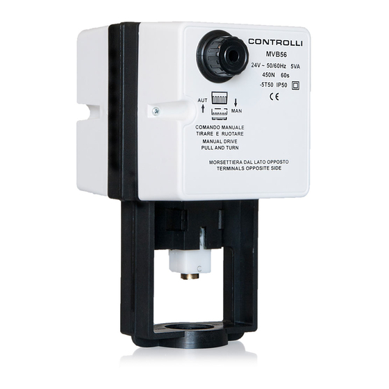
Valve Actuators
1. INSTALLATION
The actuator can be mounted in any position for applica-
tions in which the fluid temperature is not higher than 120
°C, otherwise it should be mounted in horizontal position.
It is necessary to leave 10 cm. above and beside it, so as
to operate on the internal parts, on the terminal board for
the electric connections and for assembling-disassembling
operations.
2. VSB-VMB/VSBF-VMBF/VSBPM-VMBPM/
VSBPMF-VMBPMF VALVES ASSEMBLY
(Fig.1)
• Pull and turn counter-clockwise the manual knob 1 until
the joint reaches the upper mechanical stop.
• For VSB-VMB/VSBF-VMBF: Pull out the knob 1 and
rotate clockwise (max 1/4 turn) until it enters the first
rest position.
• For VMBPM-VSBPM/VMBPMF-VSBPMF: Pull out the
knob 1 and rotate clockwise (max 1/2 turn) until it en-
ters the second rest position.
• Make sure the plug reaches upper seat by lifting the
valve stem.
• If a spacer for high temperatures is needed, insert the
MVBHT accessory 4 onto the valve neck.
• Position the actuator on the valve interposing the ring
nut 3 between the stem and the mounting bracket.
• Rotate the actuator until the bracket rests on the valve
body.
• Tighten the ring nut 3 using the supplied spanner.
• Keeping the valve stem steady, force counter-clockwise
the lower hexagonal part of joint 2 (which acts as a
locknut) until it detaches.
• Then screw clockwise the part which has been detached
so as to tighten it on the rest of the joint, thus blocking
the valve stem.
3. ACTUATOR STROKE CALIBRATION ONLY
FOR STROKES DIFFERENT FROM 16.5 mm
• Remove the back cover (opposite the knob).
• For MVB52/56 only, make sure that jumper SW2 is in A
position (Fig. 2).
• Supply the actuator between L1 and L2 terminals with Y
terminal disconnected.
• Wait the actuator to reach the lower stroke end.
• Connect the positive of the voltmeter to S2 terminal and
the negative to M.
• Rotate P1 trimmer until the voltmeter indicates 0 V.
Rev. l
CONTROLLI
ISO 9000
MOUNTING INSTRUCTIONS
11/06
CONTROLLI
16010 SANT'OLCESE Genova - Italy
Tel.: +39 01073061
E-mail: info@controlli.org
FOR MVB 36-52-56 ONLY
1
Fax: +39 0107306870/871
Web: www.controlli.org
MVB
FIG. 1
FIG. 2
N4161
N3133
DIM001E
Advertisement

Related Manuals for Controlli MVB2 Series


Summary of Contents for Controlli MVB2 Series
- Page 1 • Rotate P1 trimmer until the voltmeter indicates 0 V. N3133 FOR MVB 36-52-56 ONLY FIG. 2 Rev. l 11/06 DIM001E CONTROLLI CONTROLLI 16010 SANT’OLCESE Genova - Italy ISO 9000 Tel.: +39 01073061 Fax: +39 0107306870/871 E-mail: info@controlli.org Web: www.controlli.org...
- Page 2 P.C. board with an auxiliary potentiometer (MVBPA2) available only on request when ordering an actuator and factory-mounted. The performances stated on this sheet can be modified without any prior notice due to design improvements Rev. l 11/06 DIM001E Automatic control systems for: CONTROLLI air conditioning/heating/industrial thermal process...
Need help?
Do you have a question about the MVB2 Series and is the answer not in the manual?
Questions and answers