Advertisement
Quick Links
Advertisement

Related Manuals for OLG AXIS Caddy Bookcase 993W


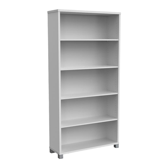
Summary of Contents for OLG AXIS Caddy Bookcase 993W
- Page 1 Bookcase Installation Guide TOOLS REQUIRED: Powered screwdriver myolgoffice.com...
- Page 2 BOOKCASE Installation Guide PARTS P A G...
- Page 3 BOOKCASE Installation Guide * To prevent possible scratches or damage, assemble the bookcase on a soft surface such as a blanket, carpet or packaging. Recommended 2-person Step STEP 1: STEP 2: Insert cam bolt (c1) and dowel pins (d1) into panels A, D, G, X and Z as Insert cam bolts (c1) and dowel pins (d1) on panel X and Z into cams on illustrated above, and assemble metal legs (m2) with screws (s1) on panel D and tighten in a clockwise direction as illustrated above.
- Page 4 BOOKCASE Installation Guide STEP 3: STEP 4: Insert cam bolts (c1) and dowel pins (d1) on panel G and A into cams Insert threaded dowel pins (p1) into panels X and Z, then put the four on panel X, Z and D, then cover the cam covers (c2) on the top of cams. panels E on the top of threaded dowel pins (p1) as illustrated above.
-
Page 5: Assembly Instruction
ASSEMBLY INSTRUCTION AXIS Cupboard 1800H ITEM No.:AXC18 PAGE... - Page 6 Incorrect Correct The arrow direction front The turning direction of attaching • PAGE...
-
Page 7: Parts List
PARTS LIST ITEM ITEM QTY. DESCRIPTION QTY. DESCRIPTION 6*35 Cam Bolt Top panel Left side panel 8*30 Dowel pin Right side panel (%") Cam Cover Back panel Threaded Dowel Pin � Bottom panel 4*16 Screw Moveable shelf Immovable panel Metal Leg Door panel Height Adjuster Door panel... - Page 8 � © 6*35 Cam Bal t-25 8*30 Dowel Pin-24 ) Cam Cover-25 4*16 Screw-50 @ Height Adjuster- 4 Threaded Dowel Pin-15 Metal Leg-4 Lock-1 © Hinge Stand-8 Hinge Body-8 Lock Catch-1 Lock Catch-1 @ Handle-2 4*22 Fix Bolt-4 Pre-installed parts @cam PAGE...
- Page 9 STEP 1 · · · · · · r ..� . . . Preparation for Top panel A, Back panel D,lmmovable panel F,Bottom panel G,Left side panel X,Right side panel Z. 1, Insert cam bolts@) and dowel pins@ into panels A ,D,F,G,X and Z as illustrated above. 2, Assemble metal legs with screws§...
- Page 10 STEP 2 Left side panel X and Right side panel Z assembly. 1 , Fix cams on panel F into cam bolts@ on panel D and tighten in a clockwise direction as illustrated above. 2, Insert cam bolts c1 and dowel pins@ on panel X and Z into cams on panel D ,F and tighten in a clockwise direction as illustrated above.
- Page 11 STEP 3 Bottom panel G and Top panel A assembly. 1, Insert cam bolts@) and dowel pins@]) on panel G and A into cams on panel X,Z and D and tighten in a clockwise direction as illustrated above. 2, Cover the cam covers@ on the top of cams. STEP 4 Moveable shelf E assembly.
- Page 12 STEP 5 � r ���� �� 1: LOOSEN ® SCREWS 2: ADJUST D'O'OR VERTICAL �PTH 3: TIGHTEN @ SCREWS AGAIN 3: TIGHTEN SCREW €)AGAIN Door panel V1 ,V2 assembly. PAGE...
- Page 13 You have now successfully completed the assembly on item: AXIS Cupboard 1800H ITEM No.:AXC18 Remove all QC and panel labels and wipe clean using a damp cloth and general household cleaner . PAGE...
- Page 14 ASSEMBLY INSTRUCTION AXIS Caddy Bookcase 993W ITEM No.:AXCMB PAGE...
- Page 15 Incorrect Correct The arrow direction front The turning direction of attaching PAGE...
-
Page 16: Item Description
PARTS LIST ITEM DESCRIPTION QTY. ITEM DESCRIPTION QTY. 6*35 Cam Bolt Top panel Left side panel 8*30 Dowel pin Right side panel (%") Cam Cover Back panel Threaded Dowel Pin Bottom panel ® Moveable shelf 4*16 Screw Vertical panel Castor �... - Page 17 STEP 1 Preparation for Top panel A, Back panel D,Bottom panel G,Left side panel X, Vertical panel Y,Right side panel Z . 1, Insert cam bolts{§} and dowel pins@ into panels A ,D,G,X,Y and Z as illustrated above. 2, Assemble castor@with screws on bottom panel G.
- Page 18 STEP 2 Cams/holes on the panel Y to face to panel X. Back panel D, Left side panel X ,Ri g ht side panel Z,Vertical panel Y assembly. 1... Fix cams on panel X,,Z, into cam bolts@) on panel D and tighten in a clockwise direction as illustrated above.
- Page 19 STEP 4 Moveable shelf E assembly. (e}) 1 � Insert threaded dowel pins into panels X,D,Y and Z as illustrated above. 2� Put the TWO panels Eon the top of threaded dowel pins @ as illustrated above. PAGE...
- Page 20 You have now successfully completed the assembly on item: AXIS Caddy Bookcase 993W ITEM No.:AXCMB Remove all QC and panel labels and wipe clean using a damp cloth and general household cleaner. PAGE...
- Page 21 ASSEMBLY INSTRUCTION AXIS System Tambour Insert-Studio ITEM No.:AXCTI PAGE...
- Page 22 11ie mTOlr directiCJll=i'rt 11ie turning direction of attaching Roller door PAGE...
- Page 23 PARTS LIST ITEM DESCRIPTION QTY. ITEM DESCRIPTION QTY. 8*35 Bott Top panel 8*30 Dowel pi'I Left side panel Right side panel <54') Cam Cover Back panel Threaded Dowel Pin Bottom panel ®) 4*16 Screw Moveable shelf (@ MO Dowel Pln-16 (@j) 4*16 Screw-4 @ 6"35 Cam Bolt-16 @ (%·)Cam Cover-16...
- Page 24 STEP 1 P19paratlon for Top panel A, Back panel D,Bottom panel G,Leftalde panel X1, Right aide panel Z . 1, Insert cam bolts@ and dowel pins into panels A .D.G,X1 and Z as illustrated above. PAGE...
- Page 25 STEP 2 Left aide panel X1 and Right aide panel Z aaaembly. 1.. Insert cam bolts@ and dowel pins 41).>n panel X1 and Z Into cams on panel D and tighten i'l a clockwis direction as Illustrated above. STEP 3 Note: All the roller doors must place into the groove of the top panel A.
- Page 26 STEP 5 Moveable shelf E assembly. 1, Insert threaded dowel pils � into panels X and Z as illustrated above. 2, Put the two panels Eon the top of threaded dowel pins �s illustrated above. STEP 6 Remove all QC and panel labels and wipe dean using a damp doth and general household clea n er •...
- Page 27 ASSEMBLY INSTRUCTION AXIS Credenza 1800W ITEM No.:AXCZ18 PAGE...
- Page 28 Incorrect Correct The arrow direction front The turning direction of attaching PAGE...
- Page 29 PARTS LIST ITEM DESCRIPTION QTY. ITEM DESCRIPTION QTY. 6*35 Cam Bolt Top panel Left side panel 8*30 Dowel pin Right side panel (%") Cam Cover Back panel Threaded Dowel Pin � Bottom panel 4*16 Screw Moveable shelf Vertical panel Metal Leg Door panel Height Adjuster Door panel...
- Page 30 � © 6*35 Cam Bal t-24 8*30 Dowel Pin-24 ) Cam Cover-24 4*16 Screw-62 @ Height Adjuster- 6 Threaded Dowel Pin-10 Metal Leg-6 Lock-2 � Lock Catch-2 Lock Catch-2 � Handle-4 4*22 Fix Bolt-8 � � � Big curve Hinge & Small curve Hinge &...
- Page 31 STEP 1 IMPORTANT: Please note the difference between parts 13 and 14. Each hinge is specifically designed for their unique position. Correct installation is essential for a successful assembly of this credenza. Preparation for Top panel A,Bottom panel G,Left side panel X,Right side panel Z,Vertical panel Y,Door panel V1,V2,V3 and V4.
- Page 32 STEP 2 Cams/holes on the panel Y to face to panel X. Top panel A, Back panel D, Left side panel X ,Right side panel Z,Vertical panel Yassembly. 1, Fix cams on panel X,Z,Y,D into cam bolts@) on panel A and tighten in a clockwise direction as illustrated above.
- Page 33 STEP 3 Bottom panel G assembly. 1 � Fix cams on panel X,Y,Z and D into cam bolts@) on panel G and tighten in a clockwise direction as illustrated above. 3, Cover the cam covers on the top of all the cams. STEP 4 Moveable shelf E assembly.
- Page 34 STEP 5 � r ��:f �� 1: LOOSEN ® SCREWS 2: ADJUST Dc:fOR VERTICAL �PTH 3: TIGHTEN @ SCREWS AGAIN 3: TIGHTEN SCREW ®AGAIN Door panel V1,V2,V3,V4 assembly. PAGE...
- Page 35 You have now successfully completed the assembly on item: AXIS Credenza 1800W ITEM No.:AXCZ18 PAGE...
- Page 36 ASSEMBLY INSTRUCTION Axis Locker Single ITEM No.:AXLOC1 PAGE...
- Page 37 Incorrect Correct The arrow direction front The turning direction of attaching PAGE...
- Page 38 PARTS LIST ITEM DESCRIPTION QTY. ITEM DESCRIPTION QTY. 6*35 Cam Bolt Top panel Left side panel 8*30 Dowel pin Right side panel (%") Cam Cover Back panel ® 4*16 Screw Bottom panel ® Immovable panel 3.5*20 Screw Batten Lock Catch �...
- Page 39 � © 6*35 Cam Bal t-29 8*30 Dowel Pin-28 @ (% ) Cam Cover-29 4*16 Screw-30 <Q;> � @ 3.5*20 Screw-12 Lock Catch-3 Lock-3 Handle-3 � � @ Hinge Stand-6 � Hinge Body-6 @ 4*22 Bolt-6 Pre-installed parts PAGE...
- Page 40 STEP 1 Preparation for Top panel A,Bottom panel G,Left side panel X,Right side panel Z,Door panel V 1, Insert cams bolts@ and dowel pins@) into panels A,G,X,and Z as illustrated above. 2, Fix hinge stands @ to panels X,Z with screws@as illustrated above. 3, Fix hinge bodies�...
- Page 41 STEP 2 Bottom panel G, Back panel Batten O assembly. 1 � Insert cam bolts€]) on panel G into cams on panel O and tighten in a clockwise direction as illustrated above. Left side panel X and Right side panel Z assembly. 1 �...
- Page 42 STEP 2 Z . . Top panel A assembly. 1, Insert cam bolts(§]) and dowel pins@ on panel A into cams on panel X,Z and D and tighten in a clockwise direction as illustrated above. 2, Cover the cam covers@ on the top of cams. PAGE...
- Page 43 STEP 5 � r ��:f �� 1: LOOSEN ® SCREWS 2: ADJUST Dc:foR VERTICAL ® �PTH 3: TIGHTEN SCREWS AGAIN 3: TIGHTEN SCREW ®AGAIN Door panel V1 ,V2 assembly. PAGE 8...
- Page 44 ASSEMBLY INSTRUCTION Axis Locker Single ITEM No.:AXLOC2 PAGE...
- Page 45 Incorrect Correct The arrow direction front The turning direction of attaching PAGE...
- Page 46 PARTS LIST ITEM DESCRIPTION QTY. ITEM DESCRIPTION QTY. 6*35 Cam Bolt Top panel Left side panel 8*30 Dowel pin Right side panel (%") Cam Cover Vertical panel ® 4*16 Screw Back panel ® Bottom panel 3.5*20 Screw Immovable panel Lock Catch �...
- Page 47 � © 6*35 Cam Bal t-48 8*30 Dowel Pin-46 @ (% ) Cam Cover-48 4*16 Screw-60 <Q;> � @ 3.5*20 Screw-24 Lock Catch-6 Lock-6 Handle-6 � � @ Hinge Stand-12 � Hinge Body-12 @ 4*22 Fix Bolt-12 Pre-installed parts PAGE...
- Page 48 STEP 1 Preparation for Top panel A,Bottom panel G,Left side panel X,Right side panel Z,Vertical panel Y,Door panel V . 1, Insert cams bolts@ and dowel pins@) into panels A,G,X,and Z as illustrated above. 2, Fix hinge stands@ to panels X,Z and Y with screws@as illustrated above. 3, Fix hinge bodies�...
- Page 49 STEP 2 ""· Bottom panel G , Back panel D and Batten O assembly. 1 � Insert cam bolts @) on panel G into cams on panel O and tighten in a clockwise direction as illustrated above. 2� Insert cam bolts @) on panel G into cams on panel D and tighten in a clockwise direction as illustrated above.
- Page 50 STEP 3 (),, Back panel D, bottom panel G,Vertical panel and Batten 0 assembly. 1.lnsert cam bolts@) on panel X and Z into cams on panels D,G,O and tighten in a clockwise direction as illustrated above. PAGE...
- Page 51 STEP 4 Top panel A ,Back panel D, Left side panel X ,Right side panel Z,Vertical panel Y .bottom panel G,Vertical panel and Batten O assembly. 1, Insert cam bolts@on panel A into cams on panels D,X,Y,Z and tighten in a clockwise direction as illustrated above.
- Page 52 STEP 5 � r ��:f �� 1: LOOSEN ® SCREWS 2: ADJUST Dc:foR VERTICAL ® �PTH 3: TIGHTEN SCREWS AGAIN 3: TIGHTEN SCREW ®AGAIN Door panel V1 ,V2 assembly. PAGE...
- Page 53 ASSEMBLY INSTRUCTION AXIS Planter for Tambour Cabinet 750W ITEM No.:AXPBOX200 PAGE...
- Page 54 Incorrect Correct The arrow direction front The turning direction of attaching PAGE...
- Page 55 PARTS LIST ITEM DESCRIPTION QTY. ITEM DESCRIPTION QTY. Side panel 6*35 Cam Bolt © Side panel 8*30 Dowel pin (%") Cam Cover Bottom panel 6*35 Cam Bolt-16 � 8*30 Dowel Pin-12 @ (%") Cam Cover-16 Pre-installed parts @cam PAGE...
- Page 56 STEP 1 Preparation for Bottom panel G, side panel 0,01 1 � Insert cam bolts@) and dowel pins@ into panels G,O and 01 as illustrated above. PAGE...
- Page 57 STEP 2 Bottom panel G, side panel O assembly. 1, Insert cam bolts@ and dowel pins@]) on panel O into cams on panel G and tighten in a clockwise direction as illustrated above. STEP 3 Side panel 0,01 assembly. 1, Insert cam bolts@ and dowel pins@ on panel 01 into cams on panel G and tighten in a clockwise direction as illustrated above.
- Page 58 STEP 4 6 PCS Transparant plastic sticker I PAGE...
- Page 59 You have now successfully completed the assembly on item: AXIS Planter for Tambour Cabinet 750W ITEM No.:AXPBOX200 Remove all QC and panel labels and wipe clean using a damp cloth and general household cleaner. PAGE...
- Page 60 ASSEMBLY INSTRUCTION AXIS Tambour Cabinet 1250H ITEM No.:AXT12 PAGE...
- Page 61 Incorrect Correct The arrow direction front The turning direction of attaching PAGE...
- Page 62 PARTS LIST ITEM DESCRIPTION QTY. ITEM DESCRIPTION QTY. 6*35 Cam Bolt Top panel Left side panel 8*30 Dowel pin Left side panel (%") Cam Cover Right side panel Threaded Dowel Pin Right side panel � ® Back panel 4*16 Screw Bottom panel Metal Leg Moveable shelf...
- Page 63 STEP 1 Preparation for Top panel A,bottom panel G,Vertical batten O,Left side panel X, X1,Right side panel Z, 21,back panel D. 1, Insert cams bolts@ and dowel pins@ into panels A,G,X,X1 ,Zand Z1 as illustrated above. 2, Insert dowel pins @ into panels D,O as illustrated above. PAGE...
- Page 64 STEP 2 Back panel D, left side panel X,X1,right side panel Z,21 and Batten O assembly. 1-. Insert cam bolts@) on panel X,X1 and Z,Z1 into cams on panels D,O and tighten in a clockwise direction as illustrated above. STEP 3 Top panel A assembly.
- Page 65 STEP 4 Note: sure the pillow components are at the bottom side. Note: All the roller doors must place into the groove of the top panel A. 12PCS PAGE...
- Page 66 STEP 5 Bottom panel G assembly. 1, Insert cam bolts(§]) on panel G into cams on panels X,X1 ,D,Z,Z1 ,0 and tighten in a clockwise direction as illustrated above. 2, Tighten the panel bottom G on the panel X,Z with fix bolt @ as illustrated above. 3, Fix Metal Leg @ to panels G with screws@as illustrated above.
- Page 67 You have now successfully completed the assembly on item: AXIS Tambour Cabinet 1250H ITEM No.:AXT12 PAGE...
- Page 68 ASSEMBLY INSTRUCTION AXIS Tambour Cabinet 900H ITEM No.:AXT9 PAGE...
- Page 69 Incorrect Correct The arrow direction front The turning direction of attaching PAGE...
- Page 70 PARTS LIST ITEM DESCRIPTION QTY. ITEM DESCRIPTION QTY. 6*35 Cam Bolt Top panel Left side panel 8*30 Dowel pin Left side panel (%") Cam Cover Right side panel Threaded Dowel Pin Right side panel � ® Back panel 4*16 Screw Bottom panel Metal Leg Moveable shelf...
- Page 71 STEP 1 X1 . . · · · · Preparation for Top panel A,bottom panel G,Vertical batten O,Left side panel X, X1,Right side panel Z, 21,back panel D. 1, Insert cams bolts@ and dowel pins@ into panels A,G,X,X1 ,Zand Z1 as illustrated above. 2, Insert dowel pins @ into panels D,O as illustrated above.
- Page 72 STEP 2 Back panel D, left side panel X,X1,right side panel Z,21 and Batten O assembly. 1-. Insert cam bolts@) on panel X,X1 and Z,Z1 into cams on panels D,O and tighten in a clockwise direction as illustrated above. STEP 3 Top panel A assembly.
- Page 73 STEP 4 Note: sure the pillow components are at the bottom side. Note: All the roller doors must place into the groove of the top panel A. 12PCS PAGE...
- Page 74 STEP 5 Bottom panel G assembly. 1, Insert cam bolts(§]) on panel G into cams on panels X,X1 ,D,Z,Z1 ,0 and tighten in a clockwise direction as illustrated above. 2, Tighten the panel bottom G on the panel X,Z with fix bolt @ as illustrated above. 3, Fix Metal Leg @ to panels G with screws@as illustrated above.
- Page 75 You have now successfully completed the assembly on item: AXIS Tambour Cabinet 900H ITEM No.:AXT9 Remove all QC and panel labels and wipe clean using a damp cloth and general household cleaner. PAGE...
- Page 76 ASSEMBLY INSTRUCTION AXIS Tambour Mobile ITEM No.:AXTM PAGE...
- Page 77 Incorrect Correct The arrow direction front The turning direction of attaching PAGE...
- Page 78 PARTS LIST ITEM DESCRIPTION QTY. ITEM DESCRIPTION QTY. Tambour Mobile Castor 4*16 Screw 4*16 Screw-16 @) Castor-4 PAGE...
- Page 79 STEP 1 Preparation for Tambour Mobile A 1 � Assemble castor @) with screws @ on bottom panel G. PAGE...
- Page 80 You have now successfully completed the assembly on item: AXIS Tambour Mobile ITEM No. :AXTM Remove all QC and panel labels and wipe clean using a damp cloth and general household cleaner. PAGE...
Need help?
Do you have a question about the AXIS Caddy Bookcase 993W and is the answer not in the manual?
Questions and answers