
Related Manuals for peerless-AV DS-LEDIF Series


Summary of Contents for peerless-AV DS-LEDIF Series
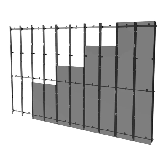
- Page 1 DS-LEDIF Series For Samsung IF015H, IF020H, IF025H *Actual configuration may vary ENG Installation video for reference only. Read and follow instruction manual for full installation. 2018-03-14 #:146-9020-9 (2020-11-18)
- Page 2 WARNING ENG - This product is designed to be installed on plywood walls. Hardware is included for plywood installation. This product is designed to be installed on flat, unobstructed, vertical walls. Do not install on curved or angled walls. Before installing make sure the supporting surface will support the combined load of the equipment and hardware.
-
Page 3: Parts List
Parts (Before beginning, make sure you have all parts shown below). Refer to parts list included with your model. Parts List Description A left column B right column C inside vertical column D top horizontal asy E bottom horizontal asy F top vertical spacer G horizontal spacer H M5 x 8mm socket screw... - Page 4 top vertical bottom vertical M5 x 8mm horizontal spacer spacer spacer #14 x 1.75" wood screw M5 square nut 3mm allen wrench two-tip T-handle wall plate connector M5 x 5mm shim plate set screw 2018-03-14 #:146-9020-9 (2020-11-18)
- Page 5 2018-03-14 #:146-9020-9 (2020-11-18)
- Page 6 Optional: If connecting two top horizontal extrusions, first remove inner hook-on brackets. Remove and save hardware. Use extrusion connectors to connect top horizontal 2.5mm extrusions. N (8) M (4) 2018-03-14 #:146-9020-9 (2020-11-18)
- Page 7 Replace one hook-on bracket in between connected extrusions. Use saved hardware. Optional: If connecting two bottom horizontal extrusions, first remove inner hook-on brackets Remove and save hardware. 2018-03-14 #:146-9020-9 (2020-11-18)
- Page 8 Use extrusion connectors to connect bottom 2.5mm horizontal extrusions. M (3) N (6) Replace one hook-on bracket in between connected extrusions. Use saved hardware. 2018-03-14 #:146-9020-9 (2020-11-18)
- Page 9 WARNING ENG - When installing Peerless wall mounts on a wood stud wall covered with plywood, verify that the wood studs are a minimum of 2" x 4" nominal size and plywood is a minimum Grade BC, 1/2" (13 mm) thick. Plywood may be covered by gypsum board (drywall) up to 5/8"...
- Page 10 7/8"(22mm) minimum Use a laser level to keep mounting holes for mounting clearance level. 2.24" (57mm) display tile 2018-03-14 #:146-9020-9 (2020-11-18)
- Page 11 Level top horizontal extrusion and mark mounting holes on plywood (must be minimum Grade BC, 1/2" (13mm) thick.) 2018-03-14 #:146-9020-9 (2020-11-18)
- Page 12 1.75" (44mm) 5/32" 5/32" (4mm) (4mm) Drill mounting holes into supporting surface (1.75" (44mm) minimum depth required). Level extrusion. Install using wood screws provided. 3/8" (10mm) Maximum 80 in. • lb (9 N.M.). 2018-03-14 #:146-9020-9 (2020-11-18)
- Page 13 Edges must be flush. Secure vertical spacers to the wall flush with the horizontal extrusion. 3/8" (10mm) 2018-03-14 #:146-9020-9 (2020-11-18)
- Page 14 Use third vertical spacer to align bottom horizontal extrusion flush with vertical spacer, then mark mounting holes on plywood (must be minimum Grade BC, 1/2" (13mm) thick.) Edges must be flush. 2018-03-14 #:146-9020-9 (2020-11-18)
- Page 15 1.75" (44mm) 5/32" 5/32" (4mm) (4mm) Drill mounting holes into supporting surface (1.75" (44mm) minimum depth required). Use third vertical spacer to align bottom horizontal extrusion flush with vertical spacer, then install using wood screws 3/8" provided. (10mm) Maximum 80 in. • lb (9 N.M.). 2018-03-14 #:146-9020-9 (2020-11-18)
- Page 16 If your video wall consists of more than four rows, proceed to step 4-1, if not proceed to step 5. 2018-03-14 #:146-9020-9 (2020-11-18)
- Page 17 Edges must be flush. For larger configurations only; Secure vertical spacer to the wall flush with the horizontal extrusion. 3/8" (10mm) 2018-03-14 #:146-9020-9 (2020-11-18)
- Page 18 Use third vertical spacer to align bottom horizontal extrusion flush with vertical spacer, then mark mounting holes on plywood (must be minimum Grade BC, 1/2" (13mm) thick.) Edges must be flush. 2018-03-14 #:146-9020-9 (2020-11-18)
- Page 19 1.75" (44mm) 5/32" 5/32" (4mm) (4mm) Drill mounting holes into supporting surface (1.75" (44mm) minimum depth required). Use third vertical spacer to align bottom horizontal extrusion flush with vertical spacer, then install using wood screws 3/8" provided. (10mm) Maximum 80 in. • lb (9 N.M.). 2018-03-14 #:146-9020-9 (2020-11-18)
- Page 20 Remove vertical spacers. 3/8" (10mm) 2018-03-14 #:146-9020-9 (2020-11-18)
- Page 21 Hook on and secure outer vertical columns. "L" and "R" markings designate left and right Tighten hardware. column. 2018-03-14 #:146-9020-9 (2020-11-18)
- Page 22 Hook on and secure all inside vertical columns. Tighten hardware. 2018-03-14 #:146-9020-9 (2020-11-18)
- Page 23 Loosen hardware on vertical columns. 2018-03-14 #:146-9020-9 (2020-11-18)
- Page 24 Plumb and level outer columns, then tighten hardware. Tighten hardware on four corner wall plates Tighten. Tighten. 2018-03-14 #:146-9020-9 (2020-11-18)
- Page 25 Tie a string between top slots on outer columns in order to level the depth of each vertical column. Loosen, adjust, tighten. Optional leveling for bowed walls Loosen. Insert. Tighten. 2018-03-14 #:146-9020-9 (2020-11-18)
- Page 26 Tie a string between bottom slots on outer columns in order to level the depth of each vertical column. Loosen, adjust, tighten. Optional leveling for bowed walls Loosen. Insert. Tighten. 2018-03-14 #:146-9020-9 (2020-11-18)
- Page 27 Tighten or loosen to adjust height. With the string still attached, level the height of each column 2018-03-14 #:146-9020-9 (2020-11-18)
- Page 28 Adjust inner columns to fit horizontal spacers. Tighten column hardware after spacing. Start from the left column. 2018-03-14 #:146-9020-9 (2020-11-18)
- Page 29 Continue adjusting inner columns to fit horizontal spacers until all are level. Tighten column hardware after spacing 2018-03-14 #:146-9020-9 (2020-11-18)
- Page 30 Remove all spacers. 2018-03-14 #:146-9020-9 (2020-11-18)
- Page 31 Optional: For shallow depth installations, flip wall bracket orientation as shown. 2.60" 2.25" (66mm) (57mm) 3.05" 2.65" (77mm) (67mm) 2018-03-14 #:146-9020-9 (2020-11-18)
- Page 32 Level L brackets and mark mounting holes on plywood (must be minimum Grade BC, 1/2" (13mm) thick.) 1.75" (44mm) 5/32" 5/32" (4mm) (4mm) Drill mounting holes into supporting surface (1.75" (44mm) minimum depth required). 2018-03-14 #:146-9020-9 (2020-11-18)
- Page 33 Level L brackets. Install using wood screws provided. 3/8" (10mm) Maximum 80 in. • lb (9 N.M.). 2018-03-14 #:146-9020-9 (2020-11-18)
- Page 34 Tie a string between center slots on outer column in order to level the depth of each vertical column. 2018-03-14 #:146-9020-9 (2020-11-18)
- Page 35 Adjust depth, then remove string. Loosen, adjust, tighten. 2018-03-14 #:146-9020-9 (2020-11-18)
- Page 36 10-1 ENG Attach display, tighten connecting hardware, and run cables one at a time starting from the bottom middle. 2018-03-14 #:146-9020-9 (2020-11-18)
- Page 37 10-2 2018-03-14 #:146-9020-9 (2020-11-18)
- Page 38 ENG To remove, start from the top edges. 2018-03-14 #:146-9020-9 (2020-11-18)
- Page 39 This page intentionally left blank. 2018-03-14 #:146-9020-9 (2020-11-18)
- Page 40 Garantia TÜR Garanti̇ Garanzia Záruka www.peerless-av.com/warranty Peerless-AV Peerless-AV Europe Peerless-AV América Latina 2300 White Oak Circle Unit 3 Watford Interchange, Av. de las Industrias 413 Aurora, IL 60502 Colonial Way, Watford, Herts, Parque Industrial Escobedo Email: tech@peerlessmounts.com WD24 4WP, United Kingdom General Escobedo N.L., México 66062...
Need help?
Do you have a question about the DS-LEDIF Series and is the answer not in the manual?
Questions and answers