Advertisement
Quick Links
Advertisement

Related Manuals for peerless-AV DS-LEDF Series


Summary of Contents for peerless-AV DS-LEDF Series
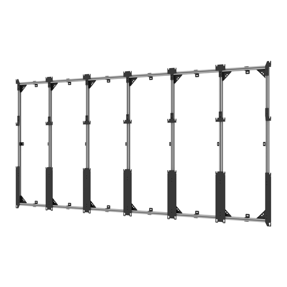
- Page 1 DS-LEDF Series *Actual configuration may vary 2016-10-28 #:146-9007-3 (2019-06-10)
- Page 2 WARNING ENG - This product is designed to be installed on plywood walls. Hardware is included for plywood installation. Before installing make sure the supporting surface will support the combined load of the equipment and hardware. Screws must be tightly secured. Do not overtighten screws or damage can occur and product may fail. Never exceed the Maximum Load Capacity.
-
Page 3: Parts List
Parts (Before beginning, make sure you have all parts shown below). Parts List Description Part # A corner bracket kit KIT-LED001-3 corner bracket asy B wall plate bracket kit KIT-LED003-3 wall plate asy wood screw C extrusion connector kit KIT-LED004A-2 extrusion connector asy D frame anchor kit KIT-LEDWP01... - Page 4 corner bracket wall plate extrusion bracket kit connector kit frame anchor corner adaptor side adaptor kit top center adaptor kit bottom center horizontal extrusion kit adaptor kit spacer kit 2016-10-28 #:146-9007-3 (2019-06-10)
- Page 5 Refer to layout drawing included for your specific model. 2016-10-28 #:146-9007-3 (2019-06-10)
- Page 6 Left and middle columns Insert corner brackets into extrusion and tighten screw to lock channel nut in place. A (2) ENG Channel nut must start ENG Tighten screw to lock in vertical position. channel nut. 2016-10-28 #:146-9007-3 (2019-06-10)
- Page 7 Right column Insert corner brackets into extrusion and tighten screw to lock channel nut in place. A (2) ENG Channel nut must start ENG Tighten screw to lock in vertical position. channel nut. 2016-10-28 #:146-9007-3 (2019-06-10)
- Page 8 Optional: Use extrusion connector if provided. Tighten connecting hardware. 2016-10-28 #:146-9007-3 (2019-06-10)
- Page 9 Secure right vertical column onto both horizontal columns. Tighten corner bracket hardware. 2016-10-28 #:146-9007-3 (2019-06-10)
- Page 10 Slide on wall plates in between vertical extrusions. Refer to layout drawing included with your model for appropriate spacing. Tighten connecting hardware. 2016-10-28 #:146-9007-3 (2019-06-10)
- Page 11 Outside spacer (I) Inside spacer (I) Slide on columns and wall plates, spacing and securing one at a time. Tighten corner bracket hardware. 2016-10-28 #:146-9007-3 (2019-06-10)
- Page 12 Insert wall plates into extrusion and tighten screws to lock channel nuts in place. Refer to layout drawing included with your model for appropriate spacing. ENG Channel nut must start ENG Tighten screw to lock in vertical position. channel nut. B (7) 2016-10-28 #:146-9007-3...
- Page 13 WARNING ENG - When installing Peerless wall mounts on a wood stud wall covered with plywood, verify that the wood studs are a minimum of 2" x 4" nominal size and plywood is a minimum Grade BC, 1/2" (13 mm) thick. Plywood may be covered by gypsum board (drywall) up to 5/8"...
- Page 14 Level wall plates and mark mounting holes on plywood (must be minimum Grade BC, 1/2" (13mm) thick.) D (6) 2016-10-28 #:146-9007-3 (2019-06-10)
- Page 15 2.5" (64mm) 5/32" 5/32" (4mm) (4mm) Drill mounting holes into supporting surface (2.5" (64mm) minimum depth required). Level wall plates. Install using wood screws provided. Maximum 80 in. • lb (9 N.M.). D (6) 3/8" (10mm) 2016-10-28 #:146-9007-3 (2019-06-10)
- Page 16 Level frame and mark mounting holes on plywood (must be minimum Grade BC, 1/2" (13mm) thick.) 2016-10-28 #:146-9007-3 (2019-06-10)
- Page 17 2.5" (64mm) 5/32" 5/32" (4mm) (4mm) Drill mounting holes into supporting surface (2.5" (64mm) minimum depth required). Level frame. Install using wood screws provided. Maximum 80 in. • lb (9 N.M.). 3/8" (10mm) 2016-10-28 #:146-9007-3 (2019-06-10)
- Page 18 Insert adaptors into extrusion and tighten screws to lock channel nuts in place. Refer to layout drawing included with your model for appropriate spacing. ENG Channel nut must start ENG Tighten screw to lock in vertical position. channel nut. 2016-10-28 #:146-9007-3 (2019-06-10)
- Page 19 Adjust adaptor height. Refer to layout drawing included for dimensions. L bracket must be flush with bottom of extrusion. 2016-10-28 #:146-9007-3 (2019-06-10)
- Page 20 Tighten all adaptor bracket and wall plate hardware. 2016-10-28 #:146-9007-3 (2019-06-10)
- Page 21 ENG Use hardware provided with adaptor kits. 1/4" (6mm) ENG Level display on Y and X axis. Tighten connecting hardware after attaching each display. 2016-10-28 #:146-9007-3 (2019-06-10)
- Page 22 ENG Tighten connecting hardware after attaching each display. ENG Optional: loosen screws to remove screens. 2016-10-28 #:146-9007-3 (2019-06-10)
- Page 23 Loosen, adjust, tighten. ENG Depth adjustment Loosen, adjust, tighten. 2016-10-28 #:146-9007-3 (2019-06-10)
-
Page 24: Limited Five-Year Warranty
(from date of the original installation of the product). At its option, Peerless-AV will repair or replace, or refund the purchase price of, any product which fails to conform with this warranty.
Need help?
Do you have a question about the DS-LEDF Series and is the answer not in the manual?
Questions and answers