
Related Manuals for Bender LINETRAXX MRCDB423


Summary of Contents for Bender LINETRAXX MRCDB423
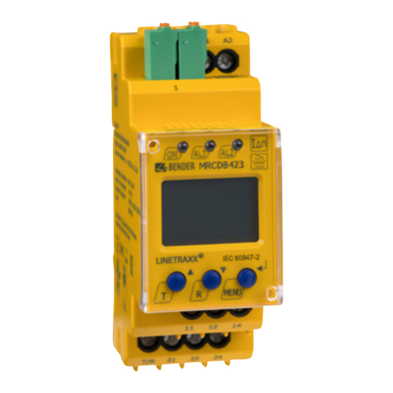
- Page 1 LINETRAXX® MRCDB423 Modular Residual Current Device type B for additional protec- tion (protection against indirect contact) in earthed systems (TN and TT systems) Manual EN MRCDB423_D00396_01_M_XXEN/06.2021...
-
Page 2: Table Of Contents
1.3 Signs and symbols ..........................3 1.4 Training courses and seminars ....................3 1.5 Delivery conditions .........................3 1.6 Inspection, transport and storage ....................4 1.7 Warranty and liability........................4 1.8 Disposal of Bender devices ......................4 1.9 Safety ..............................5 1.10 Intended use .............................5 Function ....................6 2.1 Device features ..........................6 2.2 Functional description ........................6... -
Page 3: General Instructions
Training courses and seminars www.bender.de/en -> Know-how -> Seminars. Delivery conditions The conditions of sale and delivery set out by Bender apply. These can be obtained from Bender in printed or electronic format. The following applies to software products: "Software clause in respect of the licensing of standard software as part of deliveries,... -
Page 4: Warranty And Liability
• Non-observance of technical data. • Repairs carried out incorrectly. • Use of accessories and spare parts not recommended by Bender. • Catastrophes caused by external influences and force majeure. • Mounting and installation with device combinations not recommended by the manufac- turer. -
Page 5: Safety
LINETRAXX® MRCDB423 Safety If the device is used outside the Federal Republic of Germany, the applicable local standards and regulations must be complied with. In Europe, the European standard EN 50110 applies. ! Risk of electrocution due to electric shock! Touching live parts of the system anger carries the risk of: - A fatal electric shock... -
Page 6: Function
Function Function Device features • AC/DC sensitive MRCD type B in accordance with IEC 60947-2 Annex M • Operating characteristic type B in accordance with IEC 60755 • RMS value measurement of the residual current • Alarm and prewarning indication via display and LEDs •... -
Page 7: Standard Display
While pressing and holding the test button "T", all device-relevant display elements are shown. Malfunction In the event of an internal malfunction, all three LEDs flash. The display shows an error code (E.01…E.32). In such cases, please contact the Bender Service. MRCDB423_D00396_01_M_XXEN/06.2021... -
Page 8: Time Delays T And T
Function Time delays t and t The times t and t described below delay the signalling of prewarning and main alarm via LEDs and the output relays. 2.7.1 Start-up delay t After the supply voltage U has been switched on, the device is in alarm state, which means that the output relays K1 and K2 are open and the installation is switched off. -
Page 9: Dimensions And Mounting
LINETRAXX® MRCDB423 Dimensions and mounting Dimensions 67,5 Abb. 3–1 Dimensions in mm Mounting Click & Click! Variant A: DIN rail mounting Variant B: screw mounting The front plate cover can be opened at the lower part marked with an arrow. MRCDB423_D00396_01_M_XXEN/06.2021... -
Page 10: Connection
Connection Connection ! Risk of fatal injury due to electric shock! Touching live system parts can result anger in fatal injuries. Ensure that there is no voltage in the installation area and follow the rules for working on electrical equipment. F 6A >... -
Page 11: Operation And Settings
LINETRAXX® MRCDB423 Operation and settings Function of the operating elements Device front Element Function lights continuously: Power On LED, ON (green) flashes: system fault or malfunction of connec- tion monitoring ∆n Alarm LED lights (yellow): response value I Δn1 LED TRIP lights (yellow): response value I Δn2 13 mA flow through the measuring current 13 mA... -
Page 12: Standard Display
Operation and settings Standard display On the standard display, the device alternately shows the following information during operation: currently measured value set response delay time set response value > Menu structure . . . > > Test P I N Parameter input Reset Setting ranges and factory settings... -
Page 13: Parameter Input
LINETRAXX® MRCDB423 Parameter input 5.7.1 Idn menu Setting of the response values for the alarm Idn (mA) and the prewarning (%) > > > > > > 5.7.2 t menu Setting of the response delay times t and t MRCDB423_D00396_01_M_XXEN/06.2021... - Page 14 Operation and settings 5.7.3 SEt menu Reset to factory settings System 5.7.4 InF menu The menu displays the software version of the device. The first pass is automatic; afterwards all characters can be displayed with the T button (back) and the R button (forward). Press ESC to return to the menu selection.
-
Page 15: Measuring Current Transformers
CTBCx LINETRAXX® MRCDB423 CTUB101 Measuring current transformers CTUB101-CTBC… series measuring current transformers in combination with MRCDs convert AC and DC currents into an evaluable measuring signal. They can be used in DC, AC, and 3(N)AC sys- S1(k) S2(l) tems. The shielded measuring current transformers of the CTUB101-CTBC…P series also feature a +12V -12V T full magnetic shield to prevent nuisance tripping due to external influences. -
Page 16: Fastening
Measuring current transformers Fastening Type CTBC20(P) 31.4 2 x ø 5.5 CTBC35(P) 49.8 2 x ø 5.5 CTBC60(P) 3 x ø 6.5 CTBC120(P) 103 4 x ø 6.5 CTBC210(P) 180 4 x ø 6.5 CTBC20(P), CTBC35(P) CTBC60(P) CTBC120(P) ... CTBC210(P) Mounting instructions P1 (K): YE P2 (L): GY... -
Page 17: Technical Data
LINETRAXX® MRCDB423 Technical data Displays, memory Insulation coordination acc. to IEC 60664-1/ Display range measured value AC/DC ......0…6 A IEC 60664-3 Error of measured value display ....±17.5 % / ±2 digit MRCDB423-D-1: Measured-value memory for alarm value Data record measured Rated voltage ..............100 V values Overvoltage category/pollution degree....... -
Page 18: Ordering Information
Technical data Other Operating mode ........continuous operation Position of normal use ........display-oriented Degree of protection, internal components (IEC 60529) ..IP30 Degree of protection, terminals (IEC 60529) ......IP20 Enclosure material ..........polycarbonate Flammability class ............UL94V-0 DIN rail mounting acc. to ..........IEC 60715 Screw fixing ........ -
Page 19: Error Codes
Action: – Perform a reset. Restore the factory settings of the device. The error code will be deleted automatically once the error has been eliminated. Should the error persist, please contact the Bender Service. Document revision history Date Document version... - Page 20 Nachdruck und Vervielfältigung Reprinting and duplicating nur mit Genehmigung des Herausgebers. only with permission of the publisher. Bender GmbH & Co. KG Bender GmbH & Co. KG Postfach 1161 • 35301 Grünberg • Deutschland PO Box 1161 • 35301 Grünberg • Germany Londorfer Str.
Need help?
Do you have a question about the LINETRAXX MRCDB423 and is the answer not in the manual?
Questions and answers