Table of Contents
Advertisement
Quick Links
automatic changeover and monitoring modules
Alle Rechte und Änderungen vorbehalten.
UMA710-2-xx-ISO-xx, Manual.docx
Manual
of ATICS® modules type
UMA710-2-63-ISO
UMA710-2-63-ISO-BP
UMA710-2-80-ISO
UMA710-2-80-ISO-BP
2-pole
with insulation monitoring
for medically used rooms
Subject to change without notice.
Issued: 11.Jan.2016
All rights reserved.
© Bender GmbH & Co KG
1
Advertisement
Table of Contents

Subscribe to Our Youtube Channel
Related Manuals for Bender ATICS UMA710-2-63-ISO


Summary of Contents for Bender ATICS UMA710-2-63-ISO
- Page 1 UMA710-2-63-ISO UMA710-2-63-ISO-BP UMA710-2-80-ISO UMA710-2-80-ISO-BP 2-pole automatic changeover and monitoring modules with insulation monitoring for medically used rooms Alle Rechte und Änderungen vorbehalten. Subject to change without notice. All rights reserved. © Bender GmbH & Co KG UMA710-2-xx-ISO-xx, Manual.docx Issued: 11.Jan.2016...
-
Page 2: Imprint
All rights reserved. Subject to change without notice. Reprinting only with permission of the publisher. Alle Rechte und Änderungen vorbehalten. Subject to change without notice. All rights reserved. © Bender GmbH & Co KG UMA710-2-xx-ISO-xx, Manual.docx Issued: 11.Jan.2016... -
Page 3: Table Of Contents
5.3.2. Temperature sensor .......................... 24 5.3.3. Out-going branch circuit breakers (optional) ..................24 5.3.4. Remote alarm indicator ........................25 Alle Rechte und Änderungen vorbehalten. Subject to change without notice. All rights reserved. © Bender GmbH & Co KG UMA710-2-xx-ISO-xx, Manual.docx Issued: 11.Jan.2016... - Page 4 9.4.1. Dimensions and weights ........................42 9.5. Utilisation data ........................... 42 Manufacturers certificate, checklist, documentation ................43 Appendix ............................43 Alle Rechte und Änderungen vorbehalten. Subject to change without notice. All rights reserved. © Bender GmbH & Co KG UMA710-2-xx-ISO-xx, Manual.docx Issued: 11.Jan.2016...
-
Page 5: How To Use This Operating Manual Effectively
This manual has been compiled with great care. Nevertheless errors and omissions cannot be entirely excluded. The Bender Group cannot accept any liability for injury to persons or damage to property resulting from errors or mistakes in this operating manual. -
Page 6: Safety Instructions
2.2. Skilled persons Only appropriately qualified personnel may work on Bender devices. Persons who are familiar with the assembly, commissioning and operation of the equipment and have undergone appropriate training are considered skilled persons. Such persons must have read this manual and understood all instructions relating to safety. -
Page 7: General Safety Instructions
2.4. General safety instructions Bender devices are designed and built in accordance with the state of the art and accepted rules in respect of technical safety. However, the use of such devices may introduce risks to the life and limb of the user or third parties and/or result in damage to Bender devices or other property. -
Page 8: System Description
Changeover and monitoring module for main distribution boards USC710D... Control module for changeover modules (preferably in main distribution boards) Alle Rechte und Änderungen vorbehalten. Subject to change without notice. All rights reserved. © Bender GmbH & Co KG UMA710-2-xx-ISO-xx, Manual.docx Issued: 11.Jan.2016... -
Page 9: Example Applications
MK2430 / MK800 / TM800: Alarm for at least two points with independent power supplies for functional safety Alle Rechte und Änderungen vorbehalten. Subject to change without notice. All rights reserved. © Bender GmbH & Co KG UMA710-2-xx-ISO-xx, Manual.docx Issued: 11.Jan.2016... -
Page 10: Example Intensive Care Unit
MK2430 / MK800 / TM800: Alarm for at least two points with independent power supplies for functional safety Alle Rechte und Änderungen vorbehalten. Subject to change without notice. All rights reserved. © Bender GmbH & Co KG UMA710-2-xx-ISO-xx, Manual.docx Issued: 11.Jan.2016... -
Page 11: Features Of The Uma710
The UMA710 module is a configured unit and is only certified and tested in this assembly. Do not make any changes to the components, their password-protected settings or the wiring without consulting Bender first. In each case you should make the settings that are required for adaptation to the application case in question and local conditions. -
Page 12: The Automatic Changeover Module Uma710
If the ATICS® detects a supply failure or a fault, an alarm appears on the LCD, the "ALARM" LED lights up, the alarm relay trips (if set) and this alarm is forwarded to other Bender devices (such as an alarm indicator and test combination) via the BMS bus. - Page 13 Example: Line 1 is set as the preferred line. TGH1443, chapter 3.5.1.3 Time diagram: Changeover to generator mode Alle Rechte und Änderungen vorbehalten. Subject to change without notice. All rights reserved. © Bender GmbH & Co KG UMA710-2-xx-ISO-xx, Manual.docx Issued: 11.Jan.2016...
-
Page 14: Insulation Monitoring Of The It-System
If any of the measured values does not fall within the limits, an alarm is triggered. A message appears on the LCD, the "ALARM" LED lights up, the alarm relay trips (if set) and this alarm is forwarded to other Bender devices (such as an alarm indicator and test combination) via the BMS bus. Locating current injector When an insulation fault is detected on an IT system, the integrated locating current injector generates a defined locating current signal to locate the insulation fault. -
Page 15: Power Supply
Please refer to the chapter “operation of the bypass mode”. Alle Rechte und Änderungen vorbehalten. Subject to change without notice. All rights reserved. © Bender GmbH & Co KG UMA710-2-xx-ISO-xx, Manual.docx Issued: 11.Jan.2016... -
Page 16: System Components
The following mounting racks will show some typical arrangements only. The optional bypass switch is also being showed in these examples. Alle Rechte und Änderungen vorbehalten. Subject to change without notice. All rights reserved. © Bender GmbH & Co KG UMA710-2-xx-ISO-xx, Manual.docx Issued: 11.Jan.2016... -
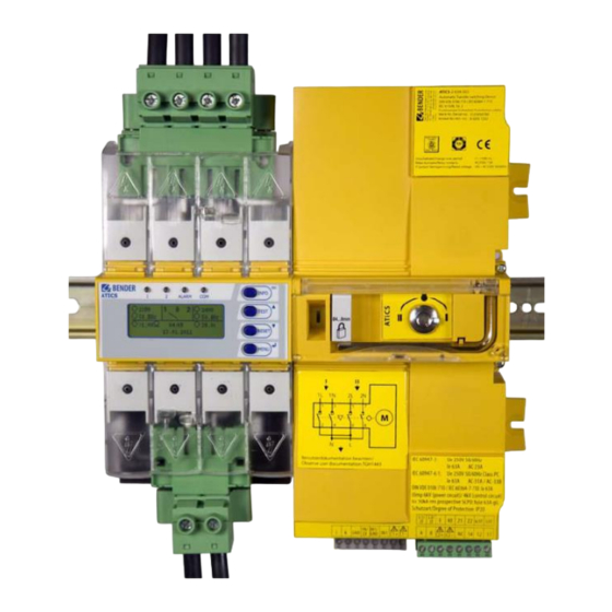
Page 17: Front View Of Atypical Uma710-2-Xx-Iso-Bp
Please refer to the attached individual, job or project related documentation like wiring diagram and elevation drawing. Alle Rechte und Änderungen vorbehalten. Subject to change without notice. All rights reserved. © Bender GmbH & Co KG UMA710-2-xx-ISO-xx, Manual.docx Issued: 11.Jan.2016... -
Page 18: Typical Mounting Arrangement Uma710-2-Xx-Iso-Bp
Please refer to the attached individual, job or project related documentation like wiring diagram and elevation drawing. Alle Rechte und Änderungen vorbehalten. Subject to change without notice. All rights reserved. © Bender GmbH & Co KG UMA710-2-xx-ISO-xx, Manual.docx Issued: 11.Jan.2016... -
Page 19: Automatic Changeover And Monitoring Unit Atics
For mounting and connection of the changeover and monitoring unit ATICS® read chapter 4 of the technical user manual TGH1443 Alle Rechte und Änderungen vorbehalten. Subject to change without notice. All rights reserved. © Bender GmbH & Co KG UMA710-2-xx-ISO-xx, Manual.docx Issued: 11.Jan.2016... -
Page 20: Typical Terminal Setup
This is only an example of a typical mounting rack arrangement only. Please refer to the attached individual, job or project related documentation like wiring diagram and elevation drawing. Alle Rechte und Änderungen vorbehalten. Subject to change without notice. All rights reserved. © Bender GmbH & Co KG UMA710-2-xx-ISO-xx, Manual.docx Issued: 11.Jan.2016... -
Page 21: Installation Of Uma710-2-Xx-Iso-Xx
As a result, the choice of fuses F should ensure both short-circuit protection for the transformer and selectivity for the overcurrent devices connected downstream in the IT systems Alle Rechte und Änderungen vorbehalten. Subject to change without notice. All rights reserved. © Bender GmbH & Co KG UMA710-2-xx-ISO-xx, Manual.docx Issued: 11.Jan.2016... - Page 22 The total current of the changeover arrangement is the total expected load current of all connected consumers. Alle Rechte und Änderungen vorbehalten. Subject to change without notice. All rights reserved. © Bender GmbH & Co KG UMA710-2-xx-ISO-xx, Manual.docx Issued: 11.Jan.2016...
-
Page 23: Changeover Module
Please refer to the attached individual, job or project related documentation like wiring diagram and elevation drawing Alle Rechte und Änderungen vorbehalten. Subject to change without notice. All rights reserved. © Bender GmbH & Co KG UMA710-2-xx-ISO-xx, Manual.docx Issued: 11.Jan.2016... -
Page 24: Notes For Connecting The Module
Protection by special installation. For this measure, please note the following: The protection class I transformer must be installed isolated and must not be connected to the PE conductor. In Bender's ES710 range of transformers, the fixing angles are isolated from the transformer core. -
Page 25: Remote Alarm Indicator
5.3.4. Remote alarm indicator Ex works, the following A+B terminals are provided for the connection of BMS bus devices: Remote alarm indicator, control panels and other Bender-BMS-bus devices can be connected to these terminals. 1. A BMS device or an existing BMS bus with several devices is connected to terminals: The last device at the other end of the bus must be terminated with 120ohm. -
Page 26: Commissioning, Settings And Testing
Setting: Response delay T(on), dead time T(0) and return transfer delay time T(2- >1). Alle Rechte und Änderungen vorbehalten. Subject to change without notice. All rights reserved. © Bender GmbH & Co KG UMA710-2-xx-ISO-xx, Manual.docx Issued: 11.Jan.2016... -
Page 27: Avoiding Errors
Please also note the information in the "BMS bus" instruction leaflet. Alle Rechte und Änderungen vorbehalten. Subject to change without notice. All rights reserved. © Bender GmbH & Co KG UMA710-2-xx-ISO-xx, Manual.docx Issued: 11.Jan.2016... -
Page 28: Example On How To Set The Addresses
** Each EDS channel shall be programmed individually to identify the branch circuit and the room in which the load is being supplied. Alle Rechte und Änderungen vorbehalten. Subject to change without notice. All rights reserved. © Bender GmbH & Co KG UMA710-2-xx-ISO-xx, Manual.docx Issued: 11.Jan.2016... -
Page 29: Operation Of The Atics® Unit
ATICS® unit again in the none-bypass/normal mode. The time in which the bypass is active in position “II” must be minimized. Alle Rechte und Änderungen vorbehalten. Subject to change without notice. All rights reserved. © Bender GmbH & Co KG UMA710-2-xx-ISO-xx, Manual.docx Issued: 11.Jan.2016... - Page 30 Before operating the bypass circuitry note the instruction on the blue label on the cover: (optional) Alle Rechte und Änderungen vorbehalten. Subject to change without notice. All rights reserved. © Bender GmbH & Co KG UMA710-2-xx-ISO-xx, Manual.docx Issued: 11.Jan.2016...
-
Page 31: Troubleshooting
CT connection Measuring current transformer - Check connecting wire of STW3 (T3), channel 7 measuring current transformer Alle Rechte und Änderungen vorbehalten. Subject to change without notice. All rights reserved. © Bender GmbH & Co KG UMA710-2-xx-ISO-xx, Manual.docx Issued: 11.Jan.2016... - Page 32 RS-485 interface failed or whether its address has changed Service __ (date) Reminder for next service - Agree date with Bender Service Test __ (date) Reminder for next test - Plan date for test - Carry out test Manual mode Message "Manual mode"...
-
Page 33: Messages With Error Code Or Service Code
4. Keep the project number, job number and drawing number, according to the type label of the changeover module or the Bender switchgear cabinet to hand. 5. Speak to Bender Service, describe the type of fault and quote the three-digit error code Please read the chapter „Frequently asked questions“ of he technical manual TGH1443 by Bender. -
Page 34: Replacements
If a replacement of the ATICS® unit is necessary after consulting our service or commissioning department the technical manual TGH1443 by Bender must be read first. Only skilled persons may work or operate the changeover and monitoring module. Skilled means, persons who are familiar with the assembly, commissioning and operation of the equipment and have undergone appropriate training. -
Page 35: Fuses F1, F2
ATICS® unit. If one of the fuse is tripped, there may be a defect in the changeover module. These fuses should only be replaced after consulting the Bender Service department. Technical data of the fuses Tripping current... -
Page 36: Periodic Verification And Service
8. Periodic verification and Service 8.1. Periodic verification The following periodic verification must be performed on electrical installations in compliance with the local or national regulations that apply. We recommend for your Bender products: Test To be Interval performed by... -
Page 37: Commissioning And Service
Londorferstr. 65 • 35305 Grünberg • Germany Tel: +49 6401 807-0 • Fax: +49 6401 807-259 E-Mail: info@bender.de • www.bender-de.com For the periodic verification of the changeover and monitoring module or switchgear systems by the Bender Service department contact: Service-Hotline: 0700-BenderHelp (Telefon and Fax) 8.3. -
Page 38: Data
The independent testing laboratory TÜV Süddeutschland, Bau und Betrieb GmbH, München, tested the changeover and monitoring module of the ATICS® series. The complete test report is available upon request. Alle Rechte und Änderungen vorbehalten. Subject to change without notice. All rights reserved. © Bender GmbH & Co KG UMA710-2-xx-ISO-xx, Manual.docx Issued: 11.Jan.2016... -
Page 39: Standards
As part of the scope of supply for the changeover and monitoring module, you will find a manufacturer's certificate in chapter "9. Manufacturer's certificate, checklist, circuit documentation" of this manual. Alle Rechte und Änderungen vorbehalten. Subject to change without notice. All rights reserved. © Bender GmbH & Co KG UMA710-2-xx-ISO-xx, Manual.docx Issued: 11.Jan.2016... -
Page 40: Technical Data
1,6 kΩ Release value Measuring time <2s PTC resistors according to DIN 44081 max. 6 in series Alle Rechte und Änderungen vorbehalten. Subject to change without notice. All rights reserved. © Bender GmbH & Co KG UMA710-2-xx-ISO-xx, Manual.docx Issued: 11.Jan.2016... - Page 41 *) For further details refer to the technical manual TGH1443 of the ATICS® changeover and monitoring unit by Bender. Alle Rechte und Änderungen vorbehalten. Subject to change without notice. All rights reserved. © Bender GmbH & Co KG UMA710-2-xx-ISO-xx, Manual.docx Issued: 11.Jan.2016...
-
Page 42: Dimensions And Weights
9700008 107659 UMA710-2-80-ISO 100A, gG 9700010 107660 UMA710-2-63-ISO-BP 80A, gG 9700007 107658 UMA710-2-63-ISO-BP 100A, gG 9700009 107585 Alle Rechte und Änderungen vorbehalten. Subject to change without notice. All rights reserved. © Bender GmbH & Co KG UMA710-2-xx-ISO-xx, Manual.docx Issued: 11.Jan.2016... -
Page 43: Manufacturers Certificate, Checklist, Documentation
Connection diagrams – Wiring diagram (showing all potentials/phases) – Elevation drawings – Wiring schematics for the BMS bus Alle Rechte und Änderungen vorbehalten. Subject to change without notice. All rights reserved. © Bender GmbH & Co KG UMA710-2-xx-ISO-xx, Manual.docx Issued: 11.Jan.2016... - Page 44 Alle Rechte und Änderungen vorbehalten. Subject to change without notice. All rights reserved. © Bender GmbH & Co KG UMA710-2-xx-ISO-xx, Manual.docx Issued: 11.Jan.2016...
Need help?
Do you have a question about the ATICS UMA710-2-63-ISO and is the answer not in the manual?
Questions and answers