
Related Manuals for Bender MEDICS UMC710D4-HA Series


Summary of Contents for Bender MEDICS UMC710D4-HA Series
- Page 1 MEDICS® UMC710D4-..HA Four-pole switchover module for medical locations with and without manual/automatic control UMC710D4_D00379_00_M_XXEN / 01.2020 Manual EN...
- Page 2 Service and support for Bender products First-level support Technical support Carl-Benz-Strasse 8 • 35305 Grünberg • Germany Telephone: +49 6401 807-760 0700BenderHelp * Fax: +49 6401 807-629 E-mail: support@bender-service.de Available on 365 days from 7.00 a.m. to 8.00 p.m. (MEZ/UTC +1) * Landline German Telekom: Mon-Fri from 9.00 a.m.
-
Page 3: Table Of Contents
1.2.1 Signs and symbols ......................5 Training courses and seminars.................5 Delivery conditions .......................5 Inspection, transport and storage ................6 Warranty and liability....................6 Disposal of Bender devices ..................6 Safety ..........................6 System describtion ................9 Intended use ........................9 Device-specific safety information .................9 MEDICS® ..........................9 UMC710D4-.. features ....................11 Functionality UMC710D4-.. - Page 4 Trouble shooting ................21 PRC487 error messages ................... 21 Fuses F1 ...F3 ........................ 22 Emergency manual mode of the changeover module ........ 23 Periodic verification and service ..........25 Periodic verification....................25 6.1.1 Testing of the changeover module ..............26 Maintenance ........................
-
Page 5: General Instructions
Training courses and seminars www.bender.de > Know-how-> Seminars. Delivery conditions The conditions of sale and delivery set out by Bender apply. These can be obtained from Bender in printed or electronic format. The following applies to software products: “Software clause in respect of the licensing of standard software as part of de-... -
Page 6: Inspection, Transport And Storage
• Non-observance of technical data. • Repairs carried out incorrectly. • Use of accessories and spare parts not recommended by Bender. • Catastrophes caused by external influences and force majeure. • Mounting and installation with device combinations not recommended by the manufac- turer. - Page 7 MEDICS® UMC710D4-..HA Before installing and connecting the device, make sure that the installation has been de-ener- gised. The rules for working on electrical systems must be observed. UMC710D4_D00379_00_M_XXEN / 01.2020...
- Page 8 System describtion UMC710D4_D00379_00_M_XXEN / 01.2020...
-
Page 9: System Describtion
The equipment can also be used in non-medical areas provided that the intended application has been cleared with Bender in advance. Please note the limits of the area of application indicated in the technical data. Use deviating from or beyond the scope of this is considered non-compliant. - Page 10 System describtion Example of a section of a hospital with the MEDICS® system UMA710... UFA710... Key for example MK... Alarm indicator and test combination RCMS... Residual current monitoring system for TN-S systems SMI472 Signal converter for third-party technical equipment (e.g. med. gases, UPS) Alarm indicator and operator panel UFA107E...
-
Page 11: Umc710D4
MEDICS® UMC710D4-..HA MEDICS® includes: • AC and 3(N)AC- changeover and monitoring modules. Examples of modules in the MEDICS® system include UMC..., USC..., UFC... and EDS..insulation fault location systems. • Display and operating units such as alarm indicator and operator panels or alarm indica- tor and test combinations. -
Page 12: Version Umc710D4
If the control device detects a supply line failure or a fault, a message appears on the LC display, the LED „ALARM“ lights up, the alarm relay switches and this alarm is transmitted to other Bender devices (such as alarm indicator and test combinations) via the BMS bus. -
Page 13: Monitoring The Device Functions
TMX-HA. System components PRC487 Control device for changeover and monitoring modules SUD487 Voltage relay BMS-Bus Bender Measuring Device Interface AN450 Power supply unit RK464, RK474 Relay module TMX-HA Alarm indicator and operator panel manual/automatic... -
Page 14: Umc710D4-160
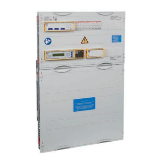
System describtion UMC710D4-160...250-HA design plan Mounting example - individual design may be different. Legend to design plan Control Section Power supply section Voltage monitoring device SUD487 5F1, 5F2 and 5F3 3-pole fuse disconnectors (see chapter “Fuses F1 ... F3“) Terminal strip X3 Terminal strip X5 Control device PRC487 Power supply unit AN450 for the supply of up to 2 alarm indicator... -
Page 15: Installation And Connection
MEDICS® UMC710D4-..HA Installation and connection Fuses Observe the requirements of IEC 60364-7-710:2002-11 and DIN VDE 0100-710 (VDE 0100 Part 710) when selecting fuses for the supply cables and outgoing circuits of the changeover modules: • Section: 710.512.1.6.2 (VDE), sections 710.5.3.1, 710.512.1.6 (IEC), Transformers for the IT system: Where transformers, their primary supply conductor and secondary outgoing line are concerned, overcurrent protective devices are only permitted for short-circuit protection. -
Page 16: Selecting A Fuse With Several Loads At One Phase Conductor
Installation and connection Changeover modules with switch disconnectors For changeover modules with switch disconnectors, the following applies: = Manufacturer‘s technical data for short-circuit protection = Manufacturer‘s technical data for rated continuous current 3.1.2 Selecting a fuse with several loads at one phase conductor Four-pole Changeover module Two-pole... -
Page 17: Instruction For Connection
X3:29 and X3:30 (A/B) X3:31 and X3:32 (A/B terminals are terminated with 120 Ω at the factory) Alarm indicator and test combinations, panels and other Bender-BMS-bus devices can be connec- ted. 1. A BMS device or an existing BMS bus with several devices is connected to terminals X3:29 and X3:30: The last device at the other end of the bus must be terminated with 120 Ω. - Page 18 Commissioning, setting and testing UMC710D4_D00379_00_M_XXEN / 01.2020...
-
Page 19: Commissioning, Setting And Testing
MEDICS® UMC710D4-..HA Commissioning, setting and testing Communication via the BMS bus can only be guaranteed when there is only one terminating resistor at the beginning and the end of the BMS bus. Additional terminating resistors can lead to malfunctions and therefore must not be used. Please also note the information in the „BMS bus“... -
Page 20: Assigning Addresses - Examples
Commissioning, setting and testing Assigning addresses - examples A changeover module with two alarm indicator and test combinations: UMC... MK... MK... Device Parameters Adress settings for a changeover module PRC487 Adress Adress First MK... Alarm adress 4, 2* Adress Second MK... Alarm adress 4, 1* Two changeover and monitoring modules, with two alarm indicator and test combinations... -
Page 21: Trouble Shooting
MEDICS® UMC710D4-..HA Trouble shooting PRC487 error messages If a fault occurs, the MEDICS® system messages will enable you to narrow down the possible cau- ses. Some messages can have several causes. The following possible errors are indicated by mes- sages in the PRC487 display. If you cannot trigger a test function on the PRC487, an alarm message may already be pending, or there may be an open circuit at terminal 9-Ub of the PRC487. -
Page 22: Fuses F1
„Manufacture´s certificate, checklist, circuit documentation“ Fuses F1 ...F3 the fuses F1...F3 are tripped, there may be a defect in the changeover module. These fuses should only be replaced following consultation with Bender. Data for fuses F1 ...F3 Tripping current �������������������������������������������������������������������������������������������������������������������������������������������������������������������� 4A , time lag rated short-circuit current ���������������������������������������������������������������������������������������������������������������������������������������������������������������100 kA... -
Page 23: Emergency Manual Mode Of The Changeover Module
MEDICS® UMC710D4-..HA Emergency manual mode of the changeover module of a total failure of the changeover module. If both switch-disconnectors are activa- arning ted at the same time, a fault on one line is also switched to the redundant line. Never activate the two switch-disconnectors simultaneously! Changeover modules are equipped with switch disconnectors. - Page 24 Trouble shooting Emergency manual operation of the motor drive Q1 or Q2 The transparent cover is opened by pushing up the release button. The PRC487 immediately signals the alarm “Open circuit Q1 (Q2) off (on)” of the corresponding switch disconnector. 208-240V AC 350VA IEC/EN 60947...
-
Page 25: Periodic Verification And Service
Functional test of the IT system monitoring by pressing the test Medical Once every button on the corresponding operating units. personnel working day (recommended by Bender) Functional test of IT system monitoring on the monitoring device. Electrically monthly (re- Functional test of the transfer switching device. skilled person commended by... -
Page 26: Testing Of The Changeover Module
Test, if necessary. ** Up to a maximum of 15 s; above this no indication possible. Bender would be delighted to provide on-site service for commissioning and periodic verificati- on. Please contact our Service Department for more information:. -
Page 27: Data, Manufacturer's Certificate, Checklist, Circuit Documentation
Data, manufacturer‘s certificate, checklist, circuit documentation TÜV-test report TÜV (Technical Inspection Authority) Service GmbH, TÜV Süd Gruppe, Munich, tested the change- over module of the MEDICS® series in 2004. The complete test report is available at Bender. UMC710D4_D00379_00_M_XXEN / 01.2020... -
Page 28: Standards
Data, manufacturer‘s certificate, checklist, circuit documentation Standards The changeover module conforms to the following standards: • DIN VDE 0100-710 (VDE 0100 Part 710):2002-11 • DIN VDE 0100-725 (VDE 0100 Part 725):1991-11 • DIN VDE 0100-718 (VDE 0100-718):2005-10 • ÖVE/ÖNORM E8007:2007-12 •... - Page 29 MEDICS® UMC710D4-..HA Cable (twisted pairs, shielded, shield connected to PE on one side) ������������������������������������������ recommended: J-Y(St)Y min� n x 2 x 0�8 Terminating resistor�����������������������������������������������������������������������������������������������������������������������������������������������������������120 Ω (0,25 W) Device address, BMS bus ���������������������������������������������������������������������������������������������������������������������������������������������������PRC487: 2…90 Factory device address ���������������������������������������������������������������������������������������������������������������������������������������������������������������PRC487: 4 Switching elements (alarm contacts PRC487) Number ��������������������������������������������������������������������������������������������������������������������������������������������������������������������1 changeover contact Operating principle ��������������������������������������������������������������������������������������������������������������������������������������������������������������N/C operation Control section connection type...
-
Page 30: Ordering Information
Data, manufacturer‘s certificate, checklist, circuit documentation Dimensions and weights Recom- Dimensions Control Dimensions Power sec- mended Weight Type section Sections/ rows tion Sections/ rows Cabinet (kg) (W /H/D mm) (W /H/D mm) depth (mm) UMC710D4-160-HA 2 / 2 (500 / 300 / 130) 2 / 3 (500 / 450 / 260) UMC710D4-250-HA 2 / 2 (500 / 300 / 130) -
Page 31: Manufacturer's Certificate, Checklist, Circuit Documentation
MEDICS® UMC710D4-..HA Accesories Material Beschreibung Artikel-Nr. TMX-HA Alarm and operator panel B92024051 TMX-HA-S with key switch B22030105 TMX-HA-PQ-PEM353N with PEM353N B22030106 TMX-HA-PQ-PEM575 with PEM575 B22030107 TMX-HA L2/L1 cable 2 left / cable 2 right B22030108 Manufacturer‘s certificate, checklist, circuit documentation The individual documents complied for your MEDICS®... - Page 32 Nachdruck und Vervielfältigung Reprinting and duplicating nur mit Genehmigung des Herausgebers. only with permission of the publisher. Bender GmbH & Co. KG Bender GmbH & Co. KG Postfach 1161 • 35301 Grünberg • Deutschland PO Box 1161 • 35301 Gruenberg • Germany Londorfer Str.
Need help?
Do you have a question about the MEDICS UMC710D4-HA Series and is the answer not in the manual?
Questions and answers