Bender LINETRAXX MRCDB300 Series Quick Start Manual
Ac/dc sensitive residual current monitoring module for mrcd applications
Hide thumbs
Also See for LINETRAXX MRCDB300 Series:
- Manual (64 pages) ,
- Quick start manual (8 pages) ,
- Manual (56 pages)

Related Manuals for Bender LINETRAXX MRCDB300 Series


Summary of Contents for Bender LINETRAXX MRCDB300 Series
- Page 1 MRCDB300 series AC/DC sensitive residual current monitoring module for MRCD applications MRCDB300-series_D00343_05_Q_XXEN/01.2022 Quickstart guide EN...
-
Page 2: Intended Use
MRCDB300 series Part of the device documentation in addition to this quick-start guide is the enclosed "Safety instructions for Bender products" and the operating manual. This quick-start guide applies to the following devices: Type Supply voltage Intended purpose Order number MRCDB301 DC 24 V (19.2…28.8 V) -
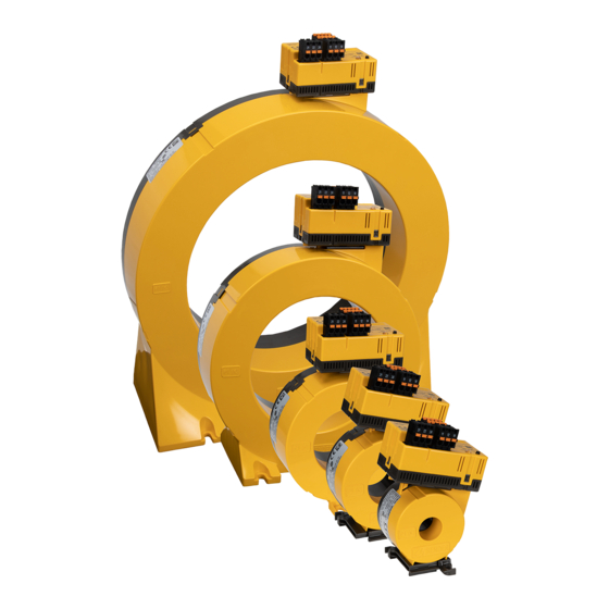
Page 3: Device View
MRCDB300 series Dimensions of mountings Type CTBC20(P) 31.4 49 2 x ø 5.5 CTBC35(P) 49.8 49 2 x ø 5.5 CTBC60(P) 2 x ø 6.5 CTBC120(P) 103 81 4 x ø 6.5 CTBC210(P) 180 98 4 x ø 6.5 CTBC20(P)/CTBC35(P) CTBC60(P) CTBC120(P)/CTBC210(P) Assembly... -
Page 4: Address Setting
MRCDB300 series Connection - N/C principle with contact feedback The use of a type 2 surge protection de- F 6 A vice (SPD) is mandatory due to possible DC 24 V 24 V impulse voltages and in order to comply MRCDB30...-CTBC... - Page 5 MRCDB300 series LED flashing modes slowly error medium mode change quickly ready for address modification slow flashing address setting mode once confirmation System state LED and output relays The LED indicates the system state by means of colours and lighting/flashing. The changeover contacts of the relay outputs K1 and K2 have defined switching positions for each system state.
-
Page 6: Offset Calibration
MRCDB300 series Offset calibration The residual current monitoring module must be calibrated to the system to be monitored so that the selected protective function can be fulfilled. Each MRCDB30… electronic module must be in- dividually calibrated to the built-in CTBC… measuring current transformer. Calibration can be car- ried out by means of the "T"... - Page 7 MRCDB300 series ! Risk of injury due to accessible live conductors! aution The measuring current transformer must be connected to the corresponding evaluator before the first use and before commissioning of the monitored system. Do not route any shielded cables through the measuring current transformer. Application in railway vehicles / DIN EN 45545-2:2016! If the horizontal or vertical distance to adjacent components which do not meet the require- ments in table 2 of DIN EN 45545-2 is less than 20 mm or less than 200 mm respectively, they...
-
Page 8: Technical Data
Nachdruck und Vervielfältigung Reprinting and duplicating nur mit Genehmigung des Herausgebers. only with permission of the publisher. Bender GmbH & Co. KG Bender GmbH & Co. KG Postfach 1161 • 35301 Grünberg • Deutschland PO Box 1161 • 35301 Grünberg • Germany Londorfer Str.
Need help?
Do you have a question about the LINETRAXX MRCDB300 Series and is the answer not in the manual?
Questions and answers