
Subscribe to Our Youtube Channel
Related Manuals for Stryker Trauma Stretcher 1037


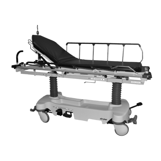
Summary of Contents for Stryker Trauma Stretcher 1037
- Page 1 Trauma Stretcher Model 1037 Maintenance Manual For parts or technical assistance: USA: 1-800-327-0770 2010/07 1037-009-002 REV A www.stryker.com...
-
Page 3: Table Of Contents
Fifth Wheel Brake Rod/Side Control Assembly........... www.stryker.com... - Page 4 Cover Assembly with Pop Up Push Handles, Head End - 1037-151-005....... . 1037-009-002 REV A www.stryker.com...
- Page 5 International Warranty Clause............www.stryker.com...
-
Page 6: Symbols And Definitions
NOTE Provides special information to make maintenance easier or important instructions clearer. Return To Table of Contents 1037-009-002 REV A www.stryker.com... -
Page 7: Introduction
Introduction This manual is designed to assist you with the operation of Stryker Model 1037 Trauma Stretcher. Read this manual thoroughly before using the equipment or beginning maintenance on it. To ensure safe operation of this equipment, it is recommended that methods and procedures be established for educating and training staff on the safe operation of this stretcher. -
Page 8: Contact Information
Stryker Medical 3800 E. Centre Avenue Portage, MI 49002 Please have the serial number (A) of your Stryker product available when calling Stryker Customer Service or Technical Support. Include the serial number in all written communication. SERIAL NUMBER LOCATION Return To Table of Contents 1037-009-002 REV A www.stryker.com... -
Page 9: Summary Of Safety Precautions
Big Wheel will be higher than normal, possibly causing damage. • To avoid injury or damage to the equipment, do not allow the siderail to lower on its own. Return To Table of Contents www.stryker.com 1037-009-002 REV A... - Page 10 • Some cleaning products are corrosive in nature and may cause damage to the product if used improperly. If the products suggested above are used to clean Stryker patient handling equipment, measures must be taken to ensure that the stretcher is wiped with a damp cloth soaked in clean water and thoroughly dried following cleaning.
-
Page 11: Setup Procedures
Raise and lower the fowler (head end). CAUTION Do not modify this stretcher. Modifying the unit can cause unpredictable operation resulting in injury to the patient or operator. Modifying the unit will also void its warranty. Return To Table of Contents www.stryker.com 1037-009-002 REV A... -
Page 12: Cleaning
Some cleaning products are corrosive in nature and may cause damage to the product if used improperly. If the products suggested above are used to clean Stryker patient handling equipment, measures must be taken to ensure that the stretcher is wiped with a damp cloth soaked in clean water and thoroughly dried following cleaning. Failure to properly rinse and dry the stretcher will leave a corrosive residue on the surface of the stretcher, possibly causing premature corrosion of critical components. -
Page 13: Mattress Cleaning
Quaternary Cleaners: identified by ingredients containing the phrase “…yl ammonium chloride” Quat/Isopropyl Cleaners: identified by a quaternary ingredient above plus isopropyl alcohol Phenolic Cleaners: identified by ingredients containing the suffix “-phenol” Chlorine Bleach: known generically as “Sodium Hypochlorite” Return To Table of Contents www.stryker.com 1037-009-002 REV A... - Page 14 Rinse surfaces which have been exposed to the solution with clear water before returning mattress to service. Note: Failure to follow the above directions when using these types of cleaners may void this product’s warranty. Return To Table of Contents 1037-009-002 REV A www.stryker.com...
-
Page 15: Preventative Maintenance
Preventative Maintenance At a minimum, preventative maintenance should be performed annually. A preventative maintenance program should be established for all Stryker Medical equipment. Preventative maintenance may need to be performed more frequently based on the usage level of the product. -
Page 16: Quick Reference Replacement Parts List
The parts and accessories listed on this page are all currently available for purchase. Some of the parts identified on the assembly drawing parts in this manual may not be individually available for purchase. Please call Stryker Customer Service USA at 1-800-327-0770 for availability and pricing. -
Page 17: Service Information
Note: When installing the new brake timing link assembly be sure to reinstall the bushing which may have fallen off during the removal of the old brake timing link assembly. 12. Verify proper operation of the unit before returning it to service. Return To Table of Contents www.stryker.com 1037-009-002 REV A... -
Page 18: Brake Swivel Lock Ring Replacement
Note: When installing the new brake timing link assembly be sure to reinstall the bushing which may have fallen off during the removal of the old brake timing link assembly. 14. Verify proper operation of the unit before returning it to service. Return To Table of Contents 1037-009-002 REV A www.stryker.com... -
Page 19: Brake Timing Link Replacement, Head End Or Foot End
Note: When installing the new brake timing link assembly be sure to reinstall the bushing which may have fallen off during the removal of the old brake timing link assembly. 10. Verify proper operation of the unit before returning it to service. Return To Table of Contents www.stryker.com 1037-009-002 REV A... -
Page 20: Brake Cam Assembly Replacement
Note: When installing the new brake cam assembly, install the bottom slightly first and then push downward and inward to install under the top bearing. 10. Verify proper operation of the unit before returning it to service. Return To Table of Contents 1037-009-002 REV A www.stryker.com... -
Page 21: Brake Rod Replacement - Fifth Wheel Only
Install the new brake rod and then install the roll pin into the head end timing link arm first. 10. Reverse steps to reinstall. 11. Verify proper operation of the unit before returning it to service. Return To Table of Contents www.stryker.com 1037-009-002 REV A... -
Page 22: Brake Rod Replacement - Big Wheel Only
Using a 5/32” Allen wrench, loosen the set screw on the head end brake rod stop collar. Remove the brake rod from the base. Reverse steps to install the new brake/steer pedal assembly. 10. Verify proper operation of the unit before returning it to service. Return To Table of Contents 1037-009-002 REV A www.stryker.com... -
Page 23: Fifth Wheel Assembly Replacement
Working from the patients left side, rotate the fifth wheel assembly counter clockwise while lifting the fifth wheel assembly up and out. 10. Reverse steps to reinstall. Torque all bolts to 13 ± 2 ft-lb. 11. Verify proper operation of the unit before returning it to service. Return To Table of Contents www.stryker.com 1037-009-002 REV A... -
Page 24: Jack Replacement, Head End - Fifth Wheel Only
15. Pump up the litter and apply weight to verify the jacks hold and do not drift. 16. Verify proper operation of the unit before returning it to service. Note: The jack descent rate is set at the factory and adjustment is not recommended. Return To Table of Contents 1037-009-002 REV A www.stryker.com... -
Page 25: Jack Replacement, Head End - Big Wheel Only
13. Pump up the litter and apply weight to verify the jacks hold and do not drift. Note: The jack descent rate is set at the factory and adjustment is not recommended. Return To Table of Contents www.stryker.com 1037-009-002 REV A... -
Page 26: Jack Replacement, Foot End - Fifth Wheel Only
14. Pump up the litter and apply weight to verify the jacks hold and do not drift. 15. Verify proper operation of the unit before returning it to service. Note: The jack descent rate is set at the factory and adjustment is not recommended. Return To Table of Contents 1037-009-002 REV A www.stryker.com... -
Page 27: Jack Removal, Foot End - Big Wheel Base With Three-Sided Controls
14. Reverse steps to reinstall. Torque all bolts to 13 ± 2 ft-lb. 15. Verify proper operation of the unit before returning it to service. Note: The jack descent rate is set at the factory and adjustment is not recommended. Return To Table of Contents www.stryker.com 1037-009-002 REV A... -
Page 28: Release Pedal (Side) Adjustment
Note: If the pedal swivel assembly is threaded too far onto the release rod, the release valve will be partially activated and the jack will drift. Return To Table of Contents 1037-009-002 REV A www.stryker.com... -
Page 29: Litter Top Removal
With the assistance of another person, lift the litter straight up to remove it from the jack shafts and set it aside. Reverse steps to reinstall the litter. Verify proper operation of the unit before returning it to service. Return To Table of Contents www.stryker.com 1037-009-002 REV A... -
Page 30: Transfer Board Counterbalance Adjustment
Too little “play” will obstruct the latch and keep it from engaging completely in the full up position, which may result in damage to the latch and/or injury to the patient or user. Return To Table of Contents 1037-009-002 REV A www.stryker.com... -
Page 31: Release Pedal Replacement, Foot End
Dislodge the side control release pedal swivels from the studs on the side control release pedal weldment. Remove the foot end pedal release rods. Reverse steps to reinstall the pedal rods. Verify proper operation of the unit before returning it to service. Return To Table of Contents www.stryker.com 1037-009-002 REV A... -
Page 32: Big Wheel Removal (Non Four-Sided Brakes)
Note: The pin is tapered, so it must be driven from the bottom up. Remove the Big Wheel. Reverse steps to reinstall the Big Wheel. Verify proper operation of the unit before returning it to service. Return To Table of Contents 1037-009-002 REV A www.stryker.com... -
Page 33: Big Wheel Dampener Replacement
Using needle nose pliers, remove the rue clip and washer and discard the gas cylinder. 10. Reverse the above steps for installation of the new brake timing link. 11. Verify proper operation of the unit before returning it to service. Return To Table of Contents www.stryker.com 1037-009-002 REV A... -
Page 34: Pneumatic Fowler Adjustment
Retighten the hex nuts. Make sure that the fowler travels from flat up to 90 degrees and down again and that it holds its position when weight is applied before returning the stretcher to service. Verify proper operation of the unit before returning it to service. Return To Table of Contents 1037-009-002 REV A www.stryker.com... -
Page 35: Removal Of Excess Air From The Hydraulic System
Verify that all hydraulic linkages are secure and operating properly. Raise the litter to its highest height. Continue to pump the pedal several times to force the air through the system. Verify proper operation before returning the unit to service. Return To Table of Contents www.stryker.com 1037-009-002 REV A... -
Page 36: Fifth Wheel Standard Brake Assembly
Torque item F to 80 ± 20 in-lb. Torque item F to 80 ± 20 in-lb. Torque item F to 80 ± 20 in-lb. Torque item F to 80 ± 20 in-lb. Return To Table of Contents 1037-009-002 REV A www.stryker.com... - Page 37 Fifth Wheel Standard Brake Assembly Torque item E to 40 ± 6 ft-lb Torque item G to 13 ± 2 ft-lb Torque item G to 13 ± 2 ft-lb Return To Table of Contents www.stryker.com 1037-009-002 REV A...
- Page 38 Stepped Flange Bearing 0853-203-201 Brake Rod Assembly (page 0853-203-230 Bearing Pivot Support 0853-303-010 Brake Link Assembly, Head End 0853-303-020 Brake Link Assembly, Foot End 0853-401-001 Base Weldment 3001-200-052 Grounding Chain 0014-003-000 Washer Return To Table of Contents 1037-009-002 REV A www.stryker.com...
-
Page 39: Fifth Wheel Brake Rod Assembly
Brake Rod Support 0853-003-055 Fifth Wheel Timing Cam Crank Assy 0853-203-011 Brake Activation Crank 0853-206-135 Fifth Wheel Drive Link Assy (page 0853-303-014 Brake Rod 1105-001-335 Label, Brake (Red) 1105-001-336 Label, Steer (Green) Return To Table of Contents www.stryker.com 1037-009-002 REV A... -
Page 40: Fifth Wheel Drive Link Assembly - 0853-206-135
Fifth Wheel Drive Link Assembly - 0853-206-135 Rev E Item Part No. Part Name Qty. 0753-003-098 Rivet 0853-206-011 Brake Rod Drive Link 0853-206-022 Fifth Wheel Cam Drive Link 0853-206-047 Fifth Wheel Cam Drive Link Return To Table of Contents 1037-009-002 REV A www.stryker.com... -
Page 41: Fifth Wheel Side Control Brake Assembly
Torque item F to 80 ± 20 in-lb. Torque item F to 80 ± 20 in-lb. Torque item F to 80 ± 20 in-lb. Torque item F to 80 ± 20 in-lb. Return To Table of Contents www.stryker.com 1037-009-002 REV A... - Page 42 Fifth Wheel Side Control Brake Assembly Torque item E to 40 ± 6 ft-lb Torque item G to 13 ± 2 ft-lb Torque item G to 13 ± 2 ft-lb Return To Table of Contents 1037-009-002 REV A www.stryker.com...
- Page 43 Fifth Wheel Side Control Brake Assembly Torque item G to 13 ± 2 ft-lb Return To Table of Contents www.stryker.com 1037-009-002 REV A...
- Page 44 Bearing Pivot Support 0853-303-010 Brake Link Assembly, Head End 0853-303-020 Brake Link Assembly, Foot End 0853-401-001 Base Weldment 1105-003-210 Side Control Brake Assembly (page 46) 1 3001-200-052 Grounding Chain 0014-003-000 Washer Return To Table of Contents 1037-009-002 REV A www.stryker.com...
-
Page 45: Fifth Wheel Brake Rod/Side Control Assembly
Brake Rod Support 0853-003-055 Fifth Wheel Timing Cam Crank Assy 0853-203-011 Brake Activation Crank 0853-206-135 Fifth Wheel Drive Link Assy (page 0853-303-014 Brake Rod 1105-001-335 Label, Brake (Red) 1105-001-336 Label, Steer (Green) Return To Table of Contents www.stryker.com 1037-009-002 REV A... -
Page 46: Fifth Wheel Side Control Brake Assembly
Rue Ring Cotter 0753-003-112 Side Control Link 0753-003-117 Rod End Link 0853-003-214 Side Control Shaft Support 1105-001-335 Label, Brake (Red) 1105-001-336 Label, Steer (Green) 1105-003-319 Side Control Brake Rod 1105-005-154 Butterfly “V” Pedal Return To Table of Contents 1037-009-002 REV A www.stryker.com... -
Page 47: Bumper Color Options - Individual Or Set Of Four
0853-003-552 Powder Blue 0853-003-553 0853-003-554 Navy 0853-003-555 Dark Lilac 0853-003-556 Bumper Color Set of Four Part Number Yellow 1105-003-551 Cool Grey 1105-003-552 Powder Blue 1105-003-553 1105-003-554 Navy 1105-003-555 Dark Lilac 1105-003-556 Return To Table of Contents www.stryker.com 1037-009-002 REV A... -
Page 48: 8" Caster With Full Cover Assembly - 0853-503-020
Caster Cover - Right 0853-003-047 Caster Cover - Left 0853-003-048 Caster Cover Plug 0853-203-030* Brake Pad Assembly 0853-303-021* Caster Horn Assembly * Shown for reference only. Individual part components are not available for sale. Return To Table of Contents 1037-009-002 REV A www.stryker.com... -
Page 49: Retractable Fifth Wheel Assembly
Torque item B to 13 ± 2 ft-lb Item Part No. Part Name Qty. 0023-288-000 Hex Washer Head Screw 0023-305-000 Hex Washer Head Screw 0753-006-148 Cam Bearing 1105-006-130 Fifth Wheel Assembly (page Return To Table of Contents www.stryker.com 1037-009-002 REV A... -
Page 50: Fifth Wheel Assembly - 1105-006-130
13 ± 2 ft-lb to 13 ± 2 ft-lb Torque item AJ to 13 ± 2 ft-lb Torque item Y to 80 ± 15 in-lb Torque item D to 13 ± 2 ft-lb Return To Table of Contents 1037-009-002 REV A www.stryker.com... - Page 51 0753-006-223 Drive Shaft 0753-006-277 Roller 1105-006-126 Fifth Wheel Bracket 1105-006-131 Fifth Wheel Weldment 0853-006-227 Return Spring Hook 0853-010-045 Hood Standoff 1210-001-147 Wheel 0023-160-000 Hex Washer Head Screw 0853-006-011 Link Stop Plate Return To Table of Contents www.stryker.com 1037-009-002 REV A...
-
Page 52: Fifth Wheel Dual Sided Hydraulics Assembly
Fifth Wheel Dual Sided Hydraulics Assembly 1105-005-500 Rev C (Reference Only) Torque item C to 13 ± 2 ft-lb Return To Table of Contents 1037-009-002 REV A www.stryker.com... - Page 53 Release Rod, Foot End 1105-004-201 Lowering Pedal Assembly (page 1105-005-035 Pump Connecting Tube Weldment 1105-005-075 Pump Pedal Link 1105-005-285 Pump Pedal Assy, Head End (page 55) 1 0853-204-014 Release Rod, Head End Return To Table of Contents www.stryker.com 1037-009-002 REV A...
-
Page 54: Lowering Pedal Assembly - 1105-004-201
Lowering Pedal Assembly - 1105-004-201 Rev A Item Part No. Part Name Qty. 0025-133-000 Dome Head Rivet 0753-004-029 Release Pedal Standoff 0853-004-320 Release Pedal Support 1105-004-004 Release Pedal Weldment 1105-201-127 Short Uni-Pedal Return To Table of Contents 1037-009-002 REV A www.stryker.com... -
Page 55: Pump Pedal Assembly, Head End - 1105-005-285
Pump Pedal Assembly, Head End - 1105-005-285 Rev B Item Part No. Part Name Qty. 0026-343-000 Groove Pin 0715-001-140 Vinyl Tube 1105-105-180 Pump Pedal Weldment, Head End 1105-201-126 Pump Pedal Return To Table of Contents www.stryker.com 1037-009-002 REV A... -
Page 56: Constant Descent Jack
Torque item A to 13 ± 2 ft-lb Torque item A to 13 ± 2 ft-lb Item Part No. Part Name Qty. 0023-288-000 Hex Washer Head Screw 0753-002-101 Constant Descent Jack Assembly 0853-010-007 Reservoir Clamp Return To Table of Contents 1037-009-002 REV A www.stryker.com... - Page 57 Big Wheel Standard Base Assembly 1115-015-305 Rev B (Reference Only) Torque item A to 18 ± 3 ft-lb Torque item A to 18 ± 3 ft-lb Return To Table of Contents www.stryker.com 1037-009-002 REV A...
- Page 58 Big Wheel Standard Base Assembly Return To Table of Contents 1037-009-002 REV A www.stryker.com...
- Page 59 Big Wheel Carriage Assembly (page 65) 1 1105-001-335 Label, Brake (Red) 1105-001-336 Label, Steer (Green) 1105-005-154 Butterfly “V” Pedal 1115-003-405 Standard Brake Assembly (page 1115-005-500 Big Wheel Dual Sided Hydraulics (page 1210-201-251 Celcon Insert Return To Table of Contents www.stryker.com 1037-009-002 REV A...
-
Page 60: Big Wheel Standard Brake Assembly
Torque item F to 80 ± 20 in-lb. Torque item F to 80 ± 20 in-lb. Torque item F to 80 ± 20 in-lb. Torque item F to 80 ± 20 in-lb. Return To Table of Contents 1037-009-002 REV A www.stryker.com... - Page 61 Big Wheel Standard Brake Assembly Torque item E to 40 ± 6 ft-lb Torque item G to 13 ± 2 ft-lb Return To Table of Contents www.stryker.com 1037-009-002 REV A...
- Page 62 Big Wheel Cam Bracket Assy (page 63) 1 1040-006-231 Drive Arm 1040-101-501 Base Weldment 1040-103-010 Brake Link Assembly, Head End 1040-103-020 Brake Link Assembly, Foot End 1210-201-251 Celcon Insert 3001-200-052 Grounding Chain 0014-003-000 Washer Return To Table of Contents 1037-009-002 REV A www.stryker.com...
-
Page 63: Big Wheel Cam Bracket Assembly - 1115-006-201
Big Wheel Cam Bracket Assembly - 1115-006-201 Rev D Return To Table of Contents www.stryker.com 1037-009-002 REV A... - Page 64 1040-006-144 Drive Link 1040-006-146 Torsion Spring 0081-305-000 Track Roller 1040-006-209 Dampener 1040-006-313 Lift Cam 1040-106-185 Dampener Arm Weldment 1115-006-221 Cam Bracket Weldment 0081-294-000 Flange Bearing 1040-025-027 Link Spacer 0081-345-000 Flange Bearing Return To Table of Contents 1037-009-002 REV A www.stryker.com...
-
Page 65: Big Wheel Carriage Assembly
Carriage Return Spring 1040-020-122 Cam Follower Pivot Pin 1040-020-128 Lift Cam Roller 1040-020-129 Carriage Guide Roller 1040-215-110 Dual Sided Control Carriage Weldment 1 1115-015-070 Big Wheel Assembly 1115-015-073 Big Wheel Cap Return To Table of Contents www.stryker.com 1037-009-002 REV A... -
Page 66: Big Wheel Dual Sided Hydraulics Assembly
Big Wheel Dual Sided Hydraulics Assembly 1115-005-500 Rev B (Reference Only) Return To Table of Contents 1037-009-002 REV A www.stryker.com... - Page 67 Big Wheel Dual Sided Hydraulics Assembly Return To Table of Contents www.stryker.com 1037-009-002 REV A...
- Page 68 Release Rod, Foot End 1040-010-215 Release Rod Bracket 1115-004-201 Lowering Pedal Assembly (page 1115-005-037 Pump Connecting Rod Weldment 1115-005-075 Pump Pedal Link 1115-005-285 Pump Pedal Assy, Head End (page 69) 1 Return To Table of Contents 1037-009-002 REV A www.stryker.com...
-
Page 69: Pump Pedal Assembly, Head End - 1115-005-285
Pump Pedal Assembly, Head End - 1115-005-285 Rev A Item Part No. Part Name Qty. 0026-343-000 Groove Pin 0715-001-140 Vinyl Tube 0753-005-044 Pump Pedal Bushing 1105-201-126 Pump Pedal Plastic 1115-005-180 Pump Pedal Weldment, Head End Return To Table of Contents www.stryker.com 1037-009-002 REV A... -
Page 70: Lowering Pedal Assembly - 1115-004-201
Lowering Pedal Assembly - 1115-004-201 Rev A Item Part No. Part Name Qty. 0025-079-000 Dome Head Rivet 0753-004-029 Release Pedal Standoff 0853-004-320 Release Pedal Support 1105-201-127 Short Uni-Pedal 1115-004-004 Release Pedal Weldment Return To Table of Contents 1037-009-002 REV A www.stryker.com... -
Page 71: Big Wheel Four-Sided Control Base Assembly
Big Wheel Four-Sided Control Base Assembly 1115-025-205 Rev B (Reference Only) Torque item A to 18 ± 3 ft-lb Torque item A to 18 ± 3 ft-lb Return To Table of Contents www.stryker.com 1037-009-002 REV A... - Page 72 Big Wheel Four-Sided Control Base Assembly Return To Table of Contents 1037-009-002 REV A www.stryker.com...
- Page 73 Carriage Pivot Bushing 1040-225-201 Side Control Carriage Assembly (page 1105-001-335 Label, Brake (Red) 1105-001-336 Label, Steer (Green) 1105-005-154 Butterfly “V” Pedal 1115-003-405 Standard Brake Assembly (page 1115-005-500 Big Wheel Dual Sided Hydraulics (page Return To Table of Contents www.stryker.com 1037-009-002 REV A...
-
Page 74: Big Wheel Side Control Carriage Assembly
Big Wheel Side Control Carriage Assembly 1040-225-201 Rev B (Reference Only) Return To Table of Contents 1037-009-002 REV A www.stryker.com... - Page 75 Side Control Pedal Spacer 1040-225-110 Four-Sided Control Carriage Weldment 1 1115-005-155 Butterfly “V” Pedal 1115-015-070 Big Wheel Assembly 1115-015-074 Big Wheel Side Control Cap 1105-001-335 Label, Brake (Red) 1105-001-336 Label, Steer (Green) Return To Table of Contents www.stryker.com 1037-009-002 REV A...
-
Page 76: Big Wheel Side Control Linkage Assembly - 1040-125-010
1040-025-013* Toggle Pivot Plate 1040-025-016* Main Link Cover 1040-025-020* Yoke Weldment 1040-125-018* Toggle Pivot Spacer 1040-025-027* Link Spacer * Shown for reference only. Individual part components are not available for sale. Return To Table of Contents 1037-009-002 REV A www.stryker.com... -
Page 77: Base Labeling Assembly, Standard Brakes
0747-010-100 Rev A (Reference Only) Item Part No. Part Name Qty. 0747-001-035 Standard Hood 0747-010-134 Dipped Bellows 0946-201-060 Label, Stryker Logo 0753-010-351 Label, Brake/Steer, Foot End 0853-010-355 Label, Lift/Lower, Left 0753-010-370 Label, Brake/Steer, Head End 0853-010-354 Label, Lift/Lower, Right Return To Table of Contents www.stryker.com... -
Page 78: Base Labeling Assembly, Four-Sided Brakes
0747-010-200 Rev A (Reference Only) Item Part No. Part Name Qty. 0747-010-034 Hood, Four-Sided Brakes 0747-010-134 Dipped Bellows 0946-201-060 Label, Stryker Logo 0853-010-018 Label, Brake/Steer, Right 0853-010-019 Label, Brake/Steer, Left 0753-010-351 Label, Brake/Steer, Foot End 0853-010-355 Label, Lift/Lower, Left 0753-010-370... -
Page 79: Base Labeling Assembly - Big Wheel Base
Item Part No. Part Name Qty. 0747-010-134 Dipped Bellows 1037-001-035 Big Wheel Hood 0946-201-060 Label, Stryker Logo 0753-010-351 Label, Brake/Steer, Foot End 0853-010-355 Label, Lift/Lower, Left 0753-010-370 Label, Brake/Steer, Head End 0853-010-354 Label, Lift/Lower, Right Return To Table of Contents www.stryker.com... -
Page 80: Litter Assembly
Litter Assembly 1037-030-010 Rev A (Reference Only) Return To Table of Contents 1037-009-002 REV A www.stryker.com... - Page 81 Litter Assembly Torque item T to 23 ± 3 ft-lb Torque item T to 23 ± 3 ft-lb Return To Table of Contents www.stryker.com 1037-009-002 REV A...
- Page 82 Litter Assembly Return To Table of Contents 1037-009-002 REV A www.stryker.com...
- Page 83 Roller Support Assembly, Right 1020-001-053 Label, Euro Centering 1020-001-059 Trend Roller Bar 1037-001-061 Litter Frame Assembly 1037-022-023 Guide Tube Assembly 1037-022-026 Adjustment Bracket 1020-022-028 Squeeze Label 1037-024-002 Litter Support Assembly, Foot End (page Return To Table of Contents www.stryker.com 1037-009-002 REV A...
- Page 84 Centering Euro-Label 1020-032-026 Foot Section Skin 1210-800-008 Patent Label 0038-220-000 Compression Spring 0001-096-000 Flat Countersunk Head Machine Screw 4 1010-001-013 Foot End Cover, Right 1010-001-014 Foot End Cover, Left 0747-026-103 Retainer Spring Return To Table of Contents 1037-009-002 REV A www.stryker.com...
-
Page 85: Litter Support Assembly, Head End - 1037-024-003
Litter Support Assembly, Head End - 1037-024-003 Rev A Item Part No. Part Name Qty. 0938-001-401 Collar 1020-024-004 Jack Support Weldment, Left 1020-024-005 Jack Support Weldment, Right 1037-010-030 Support Tube Return To Table of Contents www.stryker.com 1037-009-002 REV A... -
Page 86: Litter Support Assembly, Foot End - 1037-024-002
Hex Head Cap Screw 0016-036-000 Nylock Hex Nut 0017-003-000 Cap Nut 0025-053-000 Rivet 1037-010-029 Support Tube 0938-001-292 Support Tube Roller 0938-001-401 Collar 1010-032-064 Carrier Tube 1037-001-048 Support Tube Assembly, Foot End 0081-063-000 Bearing Return To Table of Contents 1037-009-002 REV A www.stryker.com... -
Page 87: Siderail, Left - 1010-026-017
Item Part No. Part Name Qty. 1010-026-015 Top Rail 1010-026-083 Upright 1010-026-084 Upright, Bent 1010-026-082 Sleeve Bearing 0025-106-000 Semi-Tubular Rivet 1010-026-010 Round Hole Plug 1010-026-085 Latch Upright 1010-026-012 Bent Spindle Rest Return To Table of Contents www.stryker.com 1037-009-002 REV A... -
Page 88: Siderail, Right - 1010-026-019
Item Part No. Part Name Qty. 1010-026-015 Top Rail 1010-026-083 Upright 1010-026-084 Upright, Bent 1010-026-082 Sleeve Bearing 0025-106-000 Semi-Tubular Rivet 1010-026-010 Round Hole Plug 1010-026-085 Latch Upright 1010-026-012 Bent Spindle Rest Return To Table of Contents 1037-009-002 REV A www.stryker.com... -
Page 89: Pneumatic Fowler To Litter Assembly
1037-031-025 Cylinder Mount 0016-035-000 Nylon Hex Nut 0014-021-000 Flat Washer 0003-047-000 Hex Head Cap Screw 0016-028-000 Nylon Hex Nut 1020-031-038 Fowler Rest Bumper 1037-031-017 Fowler Rest, Right 1037-031-019 Fowler Rest, Left Return To Table of Contents www.stryker.com 1037-009-002 REV A... -
Page 90: Pneumatic Fowler Assembly
Set Screw 0021-119-000 Set Screw 1010-032-066 Rectangle Hole Plug 0004-149-000 Button Head Cap Screw 0016-003-000 Nylock Hex Nut 0025-069-000 Pop Rivet 1020-023-012 Tray Handle, Left Hand 1020-023-013 Tray Latch 1020-023-014 Tray Latch Return To Table of Contents 1037-009-002 REV A www.stryker.com... -
Page 91: Transfer Board Assembly
Transfer Board System, Right (page 93) 1 1020-024-121 Board Retainer 0004-032-000 Socket Head Cap Screw 0004-142-000 Socket Head Cap Screw 0011-179-000 Nylon Washer 0016-028-000 Nylock Nut 1020-024-034 Support Plate, Left 1020-024-035 Support Plate, right Return To Table of Contents www.stryker.com 1037-009-002 REV A... -
Page 92: Transfer Board Assembly, Left - 1037-024-010
Transfer Board Assembly 0721-024-046 Label 1037-024-038 Connecting Link Assembly 1020-024-012 Pivot Arm Assembly, Left 0001-025-000 Flat Head Machine Screw 0011-224-000 Nylon Flat Washer 0016-028-000 Nylock Hex Nut 0025-157-000 Rivet 1211-132-025 Pivot Sleeve Return To Table of Contents 1037-009-002 REV A www.stryker.com... -
Page 93: Transfer Board Assembly, Right - 1037-024-011
1037-024-037 Connecting Link Assembly 1020-024-013 Pivot Arm Assembly 0001-025-000 Flat Head Machine Screw 0011-224-000 Nylon Flat Washer 0025-157-000 Rivet 0016-028-000 Nylock Hex Nut 1020-024-033 Pivot Arm Assembly, Right 1211-132-025 Pivot Sleeve Return To Table of Contents www.stryker.com 1037-009-002 REV A... -
Page 94: Arm Board Support Assembly - 1010-024-030
Arm Board Support Assembly - 1010-024-030 Rev C Item Part No. Part Name Qty. 1010-024-015 Support Block 1010-024-016 Support Arm 1010-024-014 Label, Warning 0038-263-000 Compression Spring 0008-017-000 Shoulder Bolt 1010-026-046 Ball Knob Return To Table of Contents 1037-009-002 REV A www.stryker.com... -
Page 95: X-Ray Tray Assembly, Right Side Load - 1037-022-000
X-Ray Tray Assembly, Right Side Load - 1037-022-000 1037-022-010 Rev A (Reference Only) Return To Table of Contents www.stryker.com 1037-009-002 REV A... - Page 96 1037-022-044 Frame Assembly 1020-022-025 Wheel Axle 1020-022-059 Wheel 1020-022-060 Label, Yellow 1020-022-061 X-Ray Tray Spacer 1020-022-062 Drawer Slides 0038-253-000 Extension Spring 0004-032-000 Socket Head Cap Screw 1020-021-012 Tray Indicator Weldment, Right Return To Table of Contents 1037-009-002 REV A www.stryker.com...
-
Page 97: X-Ray Tray Assembly, Left Side Load - 1037-021-000
X-Ray Tray Assembly, Left Side Load - 1037-021-000 1037-021-010 Rev A (Reference Only) Return To Table of Contents www.stryker.com 1037-009-002 REV A... - Page 98 1037-021-044 Frame Assembly 1020-022-025 Wheel Axle 1020-022-059 Wheel 1020-022-060 Label, Yellow 1020-022-061 X-Ray Tray Spacer 1020-022-062 Drawer Slides 0038-253-000 Extension Spring 0004-032-000 Socket Head Cap Screw 1020-021-017 Tray Indicator Weldment, Right Return To Table of Contents 1037-009-002 REV A www.stryker.com...
-
Page 99: X-Ray Grid Holder Assembly - 1020-027-000
1020-027-010 Rev A (Reference Only) Item Part No. Part Name Qty. 1020-027-021 Guide Weldment, Right 1020-027-022 Guide Weldment, Left 1020-027-011 Slider Weldment 0011-271-000 Fender Washer 0004-131-000 Button Head Cap Screw 1020-027-024 L Bracket Return To Table of Contents www.stryker.com 1037-009-002 REV A... -
Page 100: Optional X-Ray Centering Guide - 1020-020-000
Special Nylon Spacers 1020-022-021 Slide Block 1020-022-041 Spur Gear Modified 1020-022-043 Rack Gear Modified 1020-022-052 Guide Plate Assembly 1020-022-055 Slide Pad 1020-022-056 Centering Plate 1020-022-057 Rack Connector, Left 1020-022-058 Rack Connector Assembly Return To Table of Contents 1037-009-002 REV A www.stryker.com... -
Page 101: Optional Push Handles, Head End - 1037-151-000
1211-351-010 Push Handle Assembly (page 102) 1010-001-015 Head End Cover, Left 1010-001-016 Head End Cover, Right 0004-163-000 Hex Socket Button Head Cap Screw 0025-079-000 Dome Head Pop Rivet 1010-001-035 Handle Rest Return To Table of Contents www.stryker.com 1037-009-002 REV A... -
Page 102: Push Handle Assembly - 1211-351-010
Push Handle Assembly - 1211-351-010 Rev A Item Part No. Part Name Qty. 1010-354-024 Stop Link 1211-151-018 Sleeve Assembly 0026-118-000 Spring Pin Return To Table of Contents 1037-009-002 REV A www.stryker.com... -
Page 103: Optional Push Handles, Foot End - 1037-051-000
1000-058-019 Push Handle 1037-051-015 Handle Socket 1037-051-017 Handle Socket 1010-051-018 Rubber Bumper 0025-079-000 Pop Rivet 0026-010-000 Roll Pin 0016-028-000 Nylock Nut 0026-011-000 Roll Pin 0003-078-000 Hex Head Bolt 1010-354-024 Stop Link Return To Table of Contents www.stryker.com 1037-009-002 REV A... -
Page 104: Push Handle Assembly With I.v., Head End - 1037-151-004
Hex Socket Button Head Cap Screw 0004-163-000 Hex Socket Button Head Cap Screw 0016-028-000 Fiberlock Hex Nut 0037-074-000 Hole Plug 1010-001-013 Foot End Cover, Right 1010-001-014 Foot End Cover, Left 1037-054-067 I.V. Spacer Weldment Return To Table of Contents 1037-009-002 REV A www.stryker.com... -
Page 105: Push Handle Assembly Without I.v., Head End - 1020-151-001
Push Handle Assembly Without I.V., Head End - 1020-151-001 Rev D Item Part No. Part Name Qty. 0037-059-000 Hole Plug 1010-001-013 Foot End Cover, Right 1010-001-014 Foot End Cover, Left 0037-074-000 Hole Plug Return To Table of Contents www.stryker.com 1037-009-002 REV A... -
Page 106: Cover Assembly With Pop Up Push Handles, Head End - 1037-151-005
Cover Assembly with Pop Up Push Handles, Head End - 1037-151-005 Rev A Return To Table of Contents 1037-009-002 REV A www.stryker.com... - Page 107 Roll Pin 0037-059-000 Hole Plug 1010-001-015 Head End Cover, Left 1010-001-016 Head End Cover, Right 1010-001-035 Handle Rest 1037-054-070 Socket Assembly, Left 1037-054-071 Socket Assembly, Right 1211-351-010 Push Handle Assembly (page 102) Return To Table of Contents www.stryker.com 1037-009-002 REV A...
-
Page 108: Optional Accessories
1020-061-000 I.V. Pole, Three-Stage Permanent, Foot End 1020-062-000 I.V. Pole, Two-Stage Permanent, Foot End 1010-080-000 Oxygen Bottle Holder, Upright 1115-130-000 Serving/Instrument Tray 1105-045-700 Serving Tray Holder/Footboard 1105-045-800 Mattress and Siderail Pads Return To Table of Contents 1037-009-002 REV A www.stryker.com... -
Page 109: C-Spine Cassette Holder Assembly - 1020-070-000
Part Name Qty. 1010-070-025 I.V. Adaptor 1020-070-018 Label, Specification 0011-003-000 Washer 0004-054-000 Socket Head Screw 1010-070-010 Support Pole Assembly 1020-070-019 Storage Bracket Assembly 0037-056-000 Washer 0003-047-000 Hex Head Screw 0037-055-000 0016-005-000 Return To Table of Contents www.stryker.com 1037-009-002 REV A... -
Page 110: C-Spine Storage Bracket Assembly - 1020-070-019
C-Spine Storage Bracket Assembly - 1020-070-019 Rev A Item Part No. Part Name Qty. 1020-070-020 Storage Bracket Weldment 1010-070-045 Knob 1010-070-023 Storage Decal Return To Table of Contents 1037-009-002 REV A www.stryker.com... -
Page 111: C-Spine Support Pole Assembly - 1010-070-010
Slotted Spring Pin 1010-070-034 Support Arm Weldment 1010-070-042 Cassette Holder Weldment 1010-070-050 Adjustment Tube Weldment 1010-070-030 Base Tube Weldment 1010-070-045 Plastic Knob 0025-055-000 Pop Rivet 1010-070-044 Pivot Pin 0026-005-000 Roll Pin Return To Table of Contents www.stryker.com 1037-009-002 REV A... -
Page 112: Defibrillator Tray Assembly - 1105-045-200
Dual Lock 0029-010-000 Dual Lock 1105-045-201 Label, Defibrillator Tray 1105-045-402 Label, Push/Pull 1105-045-403 Label, Weight Capacity 1105-045-204 Tray Support 1105-045-207 Tray 0785-045-208 Bayonet 1105-045-210 Defibrillator Tray Frame Weldment 1010-050-021 Long Strap Return To Table of Contents 1037-009-002 REV A www.stryker.com... -
Page 113: Defibrillator Tray/Foot Extender/Foot Board - 1105-045-400
0785-045-405 Cushion 0785-045-410 Base Mounting Weldment 0785-045-420 Frame Pivot Weldment 0747-045-430 Tray Assembly 0785-045-450 Knob 1010-050-021 Long Strap 1010-050-242 Pin Lock 1010-050-250 Lock Adjuster 1010-050-248 Lower Pin Lock 0721-031-065 Hole Plug Return To Table of Contents www.stryker.com 1037-009-002 REV A... -
Page 114: Footboard/Chartholder Assembly - 1105-045-500
Footboard/Chartholder Assembly - 1105-045-500 Rev A Item Part No. Part Name Qty. 1105-045-402 Label, Push/Pull 1105-045-501 Label, Footboard 1105-045-511 Chartholder 1105-045-512 Footboard, Back 1105-045-513 Footboard, Front 1105-045-514 Small Standoff 1105-045-515 Large Standoff 0946-029-010 Support Return To Table of Contents 1037-009-002 REV A www.stryker.com... -
Page 115: Fowler X-Ray Cassette Assembly - 1020-023-000
Tray Hinge, Left Hand 0926-023-071 Bushing 0001-020-000 Flat Head Machine Screw 0004-149-000 Hex Socket Button Cap Screw 0001-022-000 Flat Head Screw 0016-003-000 Nylock Nut 1010-023-019 Label, Tray Removal 1020-023-027 Label, Specification Return To Table of Contents www.stryker.com 1037-009-002 REV A... -
Page 116: Heel Stirrups - 1020-055-000
Part Name Qty. 1010-055-015 Right Stirrup Support Assembly 1010-055-025 Left Stirrup Support Assembly 1010-055-029 Stirrup Assembly 0003-078-000 Hex Head Cap Screw 1020-055-015 Backer Assembly 0016-028-000 Nylock Hex Nut 0011-158-000 Flat Washer Return To Table of Contents 1037-009-002 REV A www.stryker.com... -
Page 117: Caddy - 0785-155-000
Socket Head Set Screw 0016-118-000 Hex Lock Nut 0023-288-000 Hex Washer Head Screw 0753-122-001 Clutch Assembly 0753-122-036 Boot 0753-122-103 I.V. Caddy Plate 1050-091-044 Euro Arm Assembly 1105-024-010 Label, Storage *Requires Installation Toolkit Return To Table of Contents www.stryker.com 1037-009-002 REV A... -
Page 118: Removable I.v. Pole - 0390-025-000
Removable I.V. Pole - 0390-025-000 Rev J Item Part No. Part Name Qty. 0390-003-056 Knob 0390-003-053 Double I.V. Assembly 0393-003-043 Chrome Tube Assembly 0004-496-000 Socket Head Cap Screw Return To Table of Contents 1037-009-002 REV A www.stryker.com... -
Page 119: Tethered I.v. Pole Assembly - 1001-087-018
Rev D Item Part No. Part Name Qty. 0004-495-000 Socket Head Cap Screw 0021-016-000 Set Screw 0741-047-014 Retainer 0938-001-305 Pole Socket Assembly 0938-001-308 Pole Assembly 1211-117-016 Plastic Knob 1211-117-020 Cable Assembly Return To Table of Contents www.stryker.com 1037-009-002 REV A... -
Page 120: Two-Stage I.v. Pole Assembly, Head End 1010-081-000
Part Name Qty. 0003-050-000 Hex Head Cap Screw 0004-199-000 Button Head Cap Screw 0016-036-000 Fiberlock Hex Nut 0016-028-000 Fiberlock Hex Nut 1001-059-042 Plug 1001-259-111 I.V. Pivot Weldment 1211-210-010 Two-Stage I.V. Pole Assembly Return To Table of Contents 1037-009-002 REV A www.stryker.com... -
Page 121: Three-Stage I.v. Pole Assembly, Head End 1020-061-000
Three-Stage I.V. Pole Assembly, Foot End 1020-062-000 Rev D Item Part No. Part Name Qty. 1211-211-010 Three-Stage I.V. Pole Assembly 1001-259-111 I.V. Pivot Weldment 0004-091-000 Button Head Cap Screw 0016-020-000 Centerlock Nut 1001-159-042 Plug Return To Table of Contents www.stryker.com 1037-009-002 REV A... -
Page 122: Two-Stage I.v. Pole Assembly, Foot End 1010-080-000
Part Name Qty. 0003-050-000 Hex Head Cap Screw 0004-199-000 Button Head Cap Screw 0016-036-000 Fiberlock Hex Nut 0016-028-000 Fiberlock Hex Nut 1001-059-042 Plug 1001-259-111 I.V. Pivot Weldment 1211-210-010 Two-Stage I.V. Pole Assembly Return To Table of Contents 1037-009-002 REV A www.stryker.com... -
Page 123: Upright Oxygen Bottle Holder - 1115-130-000
Upright Oxygen Bottle Holder - 1115-130-000 Rev A Item Part No. Part Name Qty. 0027-030-000 Hair Pin Cotter 1115-030-111 Upright Bottle Holder 0747-030-117 Label, Oxygen Bottle Holder Return To Table of Contents www.stryker.com 1037-009-002 REV A... -
Page 124: Serving Tray - 1105-045-700
Part Name Qty. 1105-045-701 Label, Serving Tray 0785-045-704 Flat Head Torx Screw 1105-045-705 Serving Tray Top 0785-045-706 Serving Tray Pinion 1105-045-710 Serving Tray Slider 1105-045-715 Serving Tray Cover 1105-045-403 Label, Weight Capacity Return To Table of Contents 1037-009-002 REV A www.stryker.com... -
Page 125: Foot Board/Serving Tray Holder - 1105-045-800
Foot Board/Serving Tray Holder - 1105-045-800 Rev A Item Part No. Part Name Qty. 0025-079-000 Rivet 0025-133-000 Rivet 1105-045-402 Label, Push/Pull 1105-045-801 Label, Serving Tray Holder 1105-045-805 Footboard 1105-045-810 Footboard Support Weldment 0946-001-155 Bumper Return To Table of Contents www.stryker.com 1037-009-002 REV A... -
Page 126: Mattresses And Siderail Pads
Mattress, 4” Thick x 26” Wide, Ultra Comfort............0785-034-603 Mattress, 5” Thick x 26” Wide, Ultra Comfort............0785-034-633 Mattress, 5” Thick x 26” Wide, Pioneer..............0850-026-000 Rev A Siderail Pad Set......................1010-052-000 Return To Table of Contents 1037-009-002 REV A www.stryker.com... -
Page 127: Warranty
Stryker’s obligation under this warranty is expressly limited to supplying replacement parts and labor for, or replacing, at its option, any product which is, in the sole discretion of Stryker, found to be defective. If requested by Stryker, products or parts for which a warranty claim is made shall be returned prepaid to the factory. Any improper use or any alteration or repair by others in such manner as in Stryker’s judgment affects the product materially and... -
Page 128: Service Contract Programs
Service during regular business hours (8-5) * Replacement parts and labor for products under PM contract will be discounted. ** Does not include any disposable items, I.V. poles (except for Stryker permanently attached poles), mattresses, batteries, or damage resulting from abuse. - Page 130 United States Stryker Medical 3800 E. Centre Ave., Portage, Michigan USA 49002 European Representative Stryker France ZAC Satolas Green Pusignan Av. De Satolas Green 69881 MEYZIEU Cedex France 2010/07 1037-009-002 REV A www.stryker.com...
Need help?
Do you have a question about the Trauma Stretcher 1037 and is the answer not in the manual?
Questions and answers