
Related Manuals for Canvas CANMORE 064-4014-2


Summary of Contents for Canvas CANMORE 064-4014-2
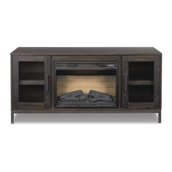
- Page 1 54” CANMORE MEDIA FIREPLACE MODEL NO. 064-4014-2 ASSEMBLY INSTRUCTIONS HAVING TROUBLE? TOLL-FREE: 1-888-670-6684...
- Page 2 We would love to hear from you and welcome your thoughtful feedback. Visit our website at canadiantire.ca to tell us about your experience, and share your photos with us using #mycanvasstyle. ® Show us how you bring CANVAS products to life. We can’t wait to see!
-
Page 3: Table Of Contents
TABLE OF CONTENTS Safety Information Parts List Step-by-step Guide Operating Instructions Cleaning and Maintenance Troubleshooting Warranty Information WARNING! TO REDUCE THE RISK OF SERIOUS INJURY, READ THE FOLLOWING SAFETY INSTRUCTIONS BEFORE ASSEMBLING AND OPERATING THIS FIREPLACE. When using electrical appliances, basic precautions should always be followed to reduce the risk of fire, electric shock and injury to persons, including the following: •... -
Page 4: Safety Information
TOOLS REQUIRED Cross-head Hex Wrench Pliers 2 people Screwdriver (Included in the package) SAFETY INFORMATION IMPORTANT SAFETY INFORMATION Use this appliance only as described in the manual. Any other use is not recommended by the manufacturer and may cause fire, electric shock or injury to persons. Read all instructions before installing or using the fireplace. - Page 5 overheats, or abnormal heating occurs, 14. Under no circumstances should this the thermostat protective device cuts fireplace be modified. Parts having off the power supply to avoid fireplace to be removed for servicing must damage and reduce the risk of fire. be replaced prior to operating this fireplace again.
-
Page 6: Parts List
PARTS LIST ITEM DESCRIPTION QUANTITY Top Panel Left Side Panel Right Side Panel Left Partition Panel Right Partition Panel Bottom Panel Middle Crossbar Left Partition Stile Right Partition Stile Metal Leg Support Rail Support Leg Door Back Panel Adjustable Shelf Remote Control with Battery Fireplace Insert Top Trim... - Page 7 CANMORE MEDIA FIREPLACE...
-
Page 8: Step-By-Step Guide
STEP-BY-STEP GUIDE STEP 1 REQUIRES A, H, I, BB Securely screw the CAM BOLTS (BB) into the designated small holes on the TOP PANEL (A) and PARTITION STILES (H and I) using a Cross-head screwdriver. X 17 Not actual size CANMORE MEDIA FIREPLACE... - Page 9 STEP 2 REQUIRES G, CC, VV Glue the WOOD DOWELS (CC) into the inner holes on the MIDDLE CROSSBAR (G) as shown. Not actual size CANMORE MEDIA FIREPLACE...
- Page 10 STEP-BY-STEP GUIDE STEP 3 REQUIRES A, G, AA Attach the MIDDLE CROSSBAR (G) to the TOP PANEL (A) by engaging three CAM LOCKS (BB). Not actual size CANMORE MEDIA FIREPLACE...
- Page 11 STEP 4 REQUIRES B, C, D, E, CC, VV Glue the WOOD DOWELS (CC) into the inner holes on the PARTITION PANELS (D and E) and SIDE PANELS (B and C) as shown. X 16 Not actual size CANMORE MEDIA FIREPLACE...
- Page 12 STEP-BY-STEP GUIDE STEP 5 REQUIRES D, E, H, I, AA Attach the LEFT PARTITION STILE (H) to the LEFT PARTITION PANEL (D) by engaging three CAM LOCKS (AA). Repeat the same procedure to attach the RIGHT PARTITION STILE (I) to the RIGHT PARTITION PANEL (E).
- Page 13 STEP 6 REQUIRES D, E, F, GG Attach the PARTITION PANELS (D and E) to the BOTTOM PANEL (F) with four LONG FLAT-HEAD SCREWS (GG). Not actual size FRONT CANMORE MEDIA FIREPLACE...
- Page 14 STEP-BY-STEP GUIDE STEP 7 REQUIRES B, C, F, GG Attach the SIDE PANELS (B and C) to the BOTTOM PANEL (F) with four LONG FLAT-HEAD SCREWS (GG). Not actual size FRONT CANMORE MEDIA FIREPLACE...
- Page 15 STEP 8 REQUIRES A, AA Ask for assistance to position the TOP PANEL (A) onto the inserted WOOD DOWELS (CC) on the vertical panels properly, and fasten it in place by engaging eight CAM LOCKS (AA). Not actual size FRONT CANMORE MEDIA FIREPLACE...
- Page 16 STEP-BY-STEP GUIDE STEP 9 REQUIRES KK, LL Ask for assistance to flip the unit around onto its front edge as shown. Attach two STRAIGHT METAL PLATES (LL) at the joints where the MIDDLE CROSSBAR (G) meets the PARTITION STILES (H and I) with four SHORT FLAT-HEAD SCREWS (KK).
- Page 17 STEP 10 REQUIRES N, II Using the pilot holes as a guide, align and attach the BACK PANELS (N) to the mantel frame with the provided WASHER-HEAD SCREWS (II). NOTE: We recommend attaching back panel with washer-head screws at the corners first.
- Page 18 STEP-BY-STEP GUIDE STEP 11 REQUIRES J, K, DD, EE, FF Attach the SUPPORT RAILS (K) to one METAL LEG (J) with four BOLTS (DD) and WASHERS (EE and FF). Not actual size CANMORE MEDIA FIREPLACE...
- Page 19 STEP 12 REQUIRES J, K, DD, EE, FF Repeat the same procedure to attach the other METAL LEG (J) at the opposite end. Not actual size CANMORE MEDIA FIREPLACE...
- Page 20 STEP-BY-STEP GUIDE STEP 13 REQUIRES HH Attach the assembled METAL LEGS (J and K) to the BOTTOM PANEL (F) with 14 MEDIUM FLAT-HEAD SCREWS (HH). X 14 Not actual size CANMORE MEDIA FIREPLACE...
- Page 21 STEP 14 REQUIRES L, JJ Attach the SUPPORT LEG (L) to the BOTTOM PANEL (F) with four PAN-HEAD SCREWS (JJ). Not actual size CANMORE MEDIA FIREPLACE...
- Page 22 STEP-BY-STEP GUIDE STEP 15 REQUIRES M, MM, NN, OO, PP Extend two HINGES (NN) and rest the hinge cups onto the cutouts of each DOOR (M). Secure the door hinges in place with two ZINC SCREWS (MM) in each. Attach one HANDLE (OO) to the front side of each door with two HANDLE BOLTS (PP).
- Page 23 STEP 16 REQUIRES MM Ask for assistance to stand the unit upright and position it near the final location. Pick up the DOORS (M) and fasten the HINGE BASES (NN) onto the SIDE PANELS (B and C) with four ZINC SCREWS (MM) in each. X 16 Not actual size CANMORE MEDIA FIREPLACE...
- Page 24 STEP-BY-STEP GUIDE STEP 17 REQUIRES 0, KK, QQ Open the doors and insert eight SHELF SUPPORTS (QQ) in the holes at the desired height inside each side compartment. Make sure you place the four shelf supports at the same level so the shelf is not tilted. Tilt and rest the ADJUSTABLE SHELVES (O) onto the shelf supports.
- Page 25 STEP 18 REQUIRES RR, SS Plug the CAM LOCK COVERS (RR) onto the visible cam locks to conceal the cams. Stick the RUBBER BUMPERS (SS) on the outer corners of doors as shown. Not actual size CANMORE MEDIA FIREPLACE...
- Page 26 STEP-BY-STEP GUIDE STEP 19 Unpack the FIREPLACE INSERT (W) from the inner box and fasten the TOP TRIM (X) to the top of the fireplace insert using two of the SHORT PAN-HEAD SCREWS (ZZ) included with the insert. Make sure that the right angle side points towards the front of the unit.
- Page 27 STEP 20 Lift the FIREPLACE INSERT (W) carefully into the back of the assembled mantel and centre it in the opening. DO NOT drag the insert across the BOTTOM PANEL (E) as it may scratch the unit. Fasten the FIREPLACE INSERT (W) to the mantel with six SHORT PAN-HEAD SCREWS (ZZ) as shown.
- Page 28 STEP-BY-STEP GUIDE STEP 21 REQUIRES TT Remove the paper backing on the ACRYLIC STOPPER (TT), then properly align the acrylic stopper into the cutout on the acrylic stopper template on the front of the TOP PANEL (A). Press down on the acrylic stopper to help adhesion. At the back of TOP PANEL (A), grip the heads of plastic tacks with pliers, and with a twisting motion, pull the tacks loose to remove the acrylic stopper template.
- Page 29 STEP 22 REQUIRES XX With assistance, position the assembled fireplace at the desired location against a wall. If necessary, adjust the pre-attached floor levellers by hand to correct tilting and level the doors until the unit is level. Follow the instructions printed on the plastic bag containing the tipping restraint hardware to attach the TIPPING RESTRAINT HARDWARE (XX) to the unit and the wall.
- Page 30 STEP-BY-STEP GUIDE STEP 23 Put the unit in place. Maximum load 80 lb (36.3 kg) Place TV behind the stopper Maximum load 50 lb (22.7 kg) WARNING! For use with televisions weighing 80 lb (36.3 kg) or less. Use with heavier televisions may cause instability and/or tip over resulting in death or serious injury.
-
Page 31: Operating Instructions
OPERATING INSTRUCTIONS IDENTIFYING THE CONTROL PANEL The control panel is located on the top right corner of the fireplace/heater unit. The control panel contains the main power (1), flame control (2) and heater control (3). 1 2 3 USING THE MAIN POWER BUTTON Press the power button (1) to turn the fireplace/heater unit on and off. - Page 32 OPERATING INSTRUCTIONS USING THE DEMO MODE For use in retail store. To turn Demo Mode on, press and hold the power button (1) for 10 seconds. The log lights flash several times to indicate that the Demo Mode is turned on. Demo Mode deactivates the heater and all front control panel buttons except the flame control button.
- Page 33 USING THE FLAME CONTROL Press the flame button (2) to set the flames for different levels of flame brightness. Control the flame brightness as shown: With the heater function on, the flame level will cycle through the 3 different level settings.
- Page 34 OPERATING INSTRUCTIONS REPLACING THE REMOTE CONTROL BATTERY The battery is supplied with the remote control. Before first use, remove the plastic sheet insulating the battery. Please follow the instructions below to replace the battery. 1. Take out the battery bracket. 2.
- Page 35 BATTERY SAFETY WARNINGS WARNING: Do not ingest batteries. • Non-rechargeable batteries are not to be recharged. • Batteries are to be inserted with the correct polarity. • Exhausted batteries are to be removed from the product. • Always purchase the correct size and grade of battery most suitable for the intended use. •...
-
Page 36: Cleaning And Maintenance
OPERATING INSTRUCTIONS DISPOSAL OF USED BATTERY A battery may contain hazardous substances that could be dangerous to the environment and human health. This symbol marked on the battery and/or packaging indicates that the used battery shall not be treated as municipal waste. Instead it should be left at an appropriate collection point for recycling. -
Page 37: Troubleshooting
TROUBLESHOOTING PROBLEM SOLUTION Using the fireplace with the heater • Fireplace is not to be used with a power strip or ON causes a trip in my power extension cord. Make sure your unit is plugged by itself circuit. into a standard qualifying wall outlet that is properly grounded. -
Page 38: Warranty Information
WARRANTY INFORMATION This CANVAS product carries a one (1) year warranty against defects in workmanship and materials. Trileaf Distribution agrees to replace the defective product free of charge within the stated warranty period, when returned by the original purchaser with proof of purchase. This product is not guaranteed against wear or breakage due to misuse and/or abuse. - Page 39 Exclusively at Canadian Tire...
- Page 41 FOYER MULTIMÉDIA CANMORE DE 54 PO DE MODÈLE : 064-4014-2 INSTRUCTIONS D’ASSEMBLAGE VOUS RENCONTREZ DES PROBLÈMES? NUMÉRO SANS FRAIS : 1 888 670-6684...
- Page 42 INSPIRÉ PAR LE CANADA Nous croyons au pouvoir de la décoration pour donner son âme à votre maison. C’est pour cela que les collections CANVAS s’inspirent des Canadiens et de leur style de vie. Qu’il s’agisse de meubles tendance, de décorations pour les fêtes ou pour le plein...
- Page 43 TABLE DES MATIÈRES Consignes de sécurité Liste des pièces Guide pas à pas Instructions d’utilisation Nettoyage et entretien Dépannage Renseignements sur la garantie AVERTISSEMENT! VEUILLEZ LIRE LES CONSIGNES DE SÉCURITÉ SUIVANTES AVANT D’ASSEMBLER ET D’UTILISER CE FOYER AFIN DE RÉDUIRE LE RISQUE DE BLESSURES GRAVES. Lors de l’utilisation d’appareils électriques, des précautions de base doivent être respectées afin de réduire le risque d’incendie, de choc électrique et de blessures, y compris ce qui suit :...
- Page 44 OUTILS REQUIS cruciforme Clé hexagonale Pince 2 personnes Tournevis (Inclus dans le paquet) CONSIGNES DE SÉCURITÉ CONSIGNES DE SÉCURITÉ IMPORTANTES Utilisez cet appareil uniquement comme indiqué dans ce guide. Toute autre utilisation non recommandée par le fabricant peut provoquer un incendie, une décharge électrique ou des blessures corporelles.
- Page 45 9. Utilisez ce radiateur uniquement 14. Ce foyer ne doit être modifié en comme décrit dans ce manuel. Toute aucun cas. Les pièces retirées pour autre utilisation non recommandée l’entretien doivent être replacées par le fabricant peut causer un avant de pouvoir utiliser le foyer à incendie, un choc électrique ou des nouveau.
- Page 46 LISTE DES PIÈCES PIÈCE DESCRIPTION QUANTITÉ Panneau supérieur Panneau latéral gauche Panneau latéral droit Panneau de séparation gauche Panneau de séparation droit Panneau inférieur Barre transversale moyenne Montant de séparation gauche Montant de séparation droit Patte en métal Traverse de soutien Patte de soutien Porte Panneau arrière...
- Page 47 FOYER MULTIMÉDIA CANMORE...
- Page 48 GUIDE ÉTAPE PAR ÉTAPE ÉTAPE 1 PIÈCES REQUISES : A, H, I, BB Vissez fermement les BOULONS DE CAME (BB) dans les petits trous désignés sur le PANNEAU SUPÉRIEUR (A) et les MONTANTS DE SÉPARATION (H et I) à l’aide d’un tournevis à...
- Page 49 ÉTAPE 2 PIÈCES REQUISES : G, CC, VV Collez les GOUJONS EN BOIS (CC) dans les trous intérieurs de la BARRE TRANSVERSALE MOYENNE (G) comme indiqué. Non illustré à taille réelle FOYER MULTIMÉDIA CANMORE...
- Page 50 GUIDE ÉTAPE PAR ÉTAPE ÉTAPE 3 PIÈCES REQUISES : A, G, AA Fixez la BARRE TRANSVERSALE MOYENNE (G) au PANNEAU SUPÉRIEUR (A) en engageant trois CAMES DE VERROUILLAGE (BB). Non illustré à taille réelle FOYER MULTIMÉDIA CANMORE...
- Page 51 ÉTAPE 4 PIÈCES REQUISES : B, C, D, E, CC, VV Collez les GOUJONS EN BOIS (CC) dans les trous intérieurs des PANNEAUX DE SÉPARATION (D et E) et des PANNEAUX LATÉRAUX (B et C) comme illustré. X 16 Non illustré à taille réelle FOYER MULTIMÉDIA CANMORE...
- Page 52 GUIDE ÉTAPE PAR ÉTAPE ÉTAPE 5 PIÈCES REQUISES : D, E, H, I, AA Attachez la POIGNÉE DE SÉPARATION GAUCHE (H) au PANNEAU DE SÉPARATION GAUCHE (D) en engageant trois CAMES DE VERROUILLAGE (AA). Répétez la même procédure pour fixer le MONTANT DE SÉPARATION DROIT (I) au PANNEAU DE SÉPARATION DROIT (E).
- Page 53 ÉTAPE 6 PIÈCES REQUISES : D, E, F, GG Fixez les PANNEAUX DE SÉPARATION (D et E) au PANNEAU INFÉRIEUR (F) au moyen de quatre LONGUES VIS À TÊTE PLATE (GG). Non illustré à taille réelle AVANT FOYER MULTIMÉDIA CANMORE...
- Page 54 GUIDE ÉTAPE PAR ÉTAPE ÉTAPE 7 PIÈCES REQUISES : B, C, F, GG Fixez les PANNEAUX LATÉRAUX (D et E) au PANNEAU INFÉRIEUR (F) au moyen de quatre LONGUES VIS À TÊTE PLATE (GG). Non illustré à taille réelle AVANT FOYER MULTIMÉDIA CANMORE...
- Page 55 ÉTAPE 8 PIÈCES REQUISES : A, AA Demandez de l’aide pour positionner correctement le PANNEAU SUPÉRIEUR (A) sur les GOUJONS DE BOIS (CC) insérés sur les panneaux verticaux, et fixez-le en place en engageant huit CAMES DE SERRURE (AA). Non illustré à taille réelle AVANT FOYER MULTIMÉDIA CANMORE...
- Page 56 GUIDE ÉTAPE PAR ÉTAPE ÉTAPE 9 PIÈCES REQUISES : KK, LL Demandez de l’aide pour retourner l’appareil sur son bord avant, comme illustré. Fixez deux PLAQUES DROITES EN MÉTAL (LL) aux joints où la BARRE TRANSVERSALE MOYENNE (G) rencontre les MONTANTS DE SÉPARATION (H et I) au moyen de quatre VIS COURTES À...
- Page 57 ÉTAPE 10 PIÈCES REQUISES : N, II En utilisant les avant-trous comme guide, alignez et fixez les PANNEAUX ARRIÈRE (N) au cadre du manteau au moyen des VIS À RONDELLE (II) fournies. REMARQUE : Nous vous recommandons de fixer le panneau arrière au moyen des vis à...
- Page 58 GUIDE ÉTAPE PAR ÉTAPE ÉTAPE 11 PIÈCES REQUISES : J, K, DD, EE, FF Fixez les TRAVERSES DE SOUTIEN (K) à une PATTE EN MÉTAL (J) au moyen de quatre BOULONS (DD) et des RONDELLES (EE et FF). Non illustré à taille réelle FOYER MULTIMÉDIA CANMORE...
- Page 59 ÉTAPE 12 PIÈCES REQUISES : J, K, DD, EE, FF Répétez la même procédure pour fixer l’autre PATTE EN MÉTAL (J) à l’extrémité opposée. Non illustré à taille réelle FOYER MULTIMÉDIA CANMORE...
- Page 60 GUIDE ÉTAPE PAR ÉTAPE ÉTAPE 13 PIÈCE REQUISE : HH Fixez les PATTES EN MÉTAL (J et K) assemblées au PANNEAU INFÉRIEUR (F) au moyen des 14 VIS MOYENNES À TÊTE PLATE (HH). X 14 Non illustré à taille réelle FOYER MULTIMÉDIA CANMORE...
- Page 61 ÉTAPE 14 PIÈCES REQUISES : L, JJ Fixez la PATTE DE SOUTIEN (L) au PANNEAU INFÉRIEUR (F) au moyen de quatre VIS À TÊTE CYLINDRIQUE (JJ). Non illustré à taille réelle FOYER MULTIMÉDIA CANMORE...
- Page 62 GUIDE ÉTAPE PAR ÉTAPE ÉTAPE 15 PIÈCES REQUISES : M, MM, NN, OO, PP Déployez deux CHARNIÈRES (NN) et posez les coupelles de charnière sur les découpes de chaque PORTE (M). Fixez les charnières de porte en place au moyen de deux VIS EN ZINC (MM) dans chacune.
- Page 63 ÉTAPE 16 PIÈCE REQUISE : MM Demandez de l’aide pour redresser l’appareil et le positionner près de l’emplacement final. Prenez les PORTES (M) et fixez les BASES DE CHARNIÈRE (NN) sur les PANNEAUX LATÉRAUX (B et C) au moyen de quatre VIS EN ZINC (MM) dans chacune. X 16 Non illustré...
- Page 64 GUIDE ÉTAPE PAR ÉTAPE ÉTAPE 17 PIÈCES REQUISES : 0, KK, QQ Ouvrez les portes et insérez huit TAQUETS (QQ) dans les trous à la hauteur désirée à l’intérieur de chaque compartiment latéral. Assurez-vous de placer les quatre taquets au même niveau afin que la tablette ne soit pas inclinée. Inclinez et posez les TABLETTES AJUSTABLES (O) sur les taquets.
- Page 65 ÉTAPE 18 PIÈCES REQUISES : RR, SS Posez les CACHES DE CAME DE VERROUILLAGE (RR) sur les cames de verrouillage visibles pour masquer les cames. Collez les PARE-CHOCS EN CAOUTCHOUC (SS) sur les coins extérieurs des portes comme illustré. Non illustré à taille réelle FOYER MULTIMÉDIA CANMORE...
- Page 66 GUIDE ÉTAPE PAR ÉTAPE ÉTAPE 19 Déballez le FOYER ENCASTRABLE (W) de la boîte interne et fixez la GARNITURE SUPÉRIEURE (X) au haut du foyer encastrable au moyen de deux PETITE VIS À TÊTE CYLINDRIQUE BOMBÉE (ZZ) vis fournies avec le foyer encastrable. Assurez-vous que le côté...
- Page 67 ÉTAPE 20 Soulevez le foyer encastrable avec précaution à l’arrière du manteau assemblé et centrez-le dans l’ouverture. Ne faites PAS glisser le foyer encastrable sur le PANNEAU INFÉRIEUR (E) car cela pourrait rayer l’appareil. Fixez le FOYER ENCASTRABLE (W) au manteau au moyen de six PETITE VIS À TÊTE CYLINDRIQUE BOMBÉE (ZZ) du foyer comme illustré.
- Page 68 GUIDE ÉTAPE PAR ÉTAPE ÉTAPE 21 PIÈCE REQUISE : TT Retirez le papier d’endos de la BUTÉE EN ACRYLIQUE (TT), puis alignez correctement la butée acrylique dans la découpe du gabarit de la butée acrylique à l’avant du PANNEAU SUPÉRIEUR (A). Appuyez sur la butée acrylique pour obtenir une meilleure adhérence.
- Page 69 ÉTAPE 22 PIÈCE REQUISE : XX Avec de l’aide, placez le foyer assemblé à l’endroit désiré contre un mur. Si nécessaire, ajustez les pieds de nivellement préfixés à la main pour corriger l’inclinaison et niveler les portes jusqu’à ce que l’appareil soit de niveau. Suivez les instructions imprimées sur le sac en plastique contenant le matériel de retenue de basculement pour fixer le MATÉRIEL DE RETENUE ANTIBASCULEMENT (XX) à...
- Page 70 GUIDE ÉTAPE PAR ÉTAPE ÉTAPE 23 Mettez l’appareil en place. Charge maximale 80 lb (36,3 kg) Placez le téléviseur derrière la butée Charge maximale 50 lb (22,7 kg) AVERTISSEMENT! Pour une utilisation avec des téléviseurs pesant 80 lb (36,3 kg) ou moins. Des téléviseurs plus lourds peuvent provoquer une instabilité...
- Page 71 MODE D’EMPLOI PANNEAU DE COMMANDE Le panneau de commande est situé dans le coin supérieur droit du foyer/appareil de chauffage. Le panneau de commande comprend le bouton interrupteur d’alimentation (1), la commande de flamme (2) et la commande de chauffage (3). 1 2 3 UTILISATION DU BOUTON INTERRUPTEUR Appuyez sur le bouton interrupteur (1) pour allumer et éteindre le foyer/l’appareil de...
- Page 72 MODE D’EMPLOI UTILISATION DU MODE DÉMO Pour une utilisation dans un magasin de détail. Pour activer le mode démo, appuyez sur le bouton interrupteur d’alimentation (1) pendant 10 secondes. Les lumières de bûche clignotent plusieurs fois pour indiquer que le mode démo est activé.
- Page 73 UTILISATION DE LA COMMANDE DE FLAMME Appuyez sur le bouton de commande de flamme (2) pour régler les flammes pour différents niveaux de luminosité de la flamme. Contrôlez la luminosité de la flamme comme indiqué : Appuis sur bouton Niveau d’effet de flamme Apparence du foyer 1er appui Moyenne Flammes moyennes, bûches de luminosité...
- Page 74 MODE D’EMPLOI REMPLACEMENT DE LA PILE DE LA TÉLÉCOMMANDE La pile est fournie avec la télécommande. Avant la première utilisation, retirez la pellicule de plastique isolant la pile. Veuillez suivre les instructions ci-dessous pour remplacer la pile. 1. Retirez le support de la pile. 2.
- Page 75 AVERTISSEMENTS DE SÉCURITÉ CONCERNANT LES PILES AVERTISSEMENT : N’avalez pas de piles. • Les piles non rechargeables ne doivent pas être rechargées. • Assurez-vous que la polarité des piles installées est correcte. • Une pile épuisée doit être retirée de la télécommande. •...
- Page 76 MODE D’EMPLOI ÉLIMINATION DES PILES USAGÉES Une pile peut contenir des substances dangereuses qui pourraient être nocives pour l’environnement et la santé humaine. Ce symbole inscrit sur la pile ou l’emballage indique que la pile usagée ne doit pas être traitée comme un déchet municipal.
- Page 77 TROUBLESHOOTING PROBLÈME SOLUTION L’utilisation du foyer avec la • Le foyer ne doit pas être utilisé avec une multiprise ou une fonction de chauffage activé rallonge. Assurez-vous que votre appareil est branché seul provoque un déclenchement dans sur une prise murale de qualification standard correctement le circuit d’alimentation mise à...
- Page 78 GARANTIE GARANTIE LIMITÉE DE 1 ANS* Cet article CANVAS comprend une garantie de un (1) an contre les défauts de fabrication et de matériau(x). Distribution Trifeuil consent à remplacer l’article défectueux lorsqu’il est retourné par l’acheteur original, accompagné de la preuve d’achat, au cours de la période de garantie convenue.
- Page 79 En exclusivité chez Canadian Tire...
Need help?
Do you have a question about the CANMORE 064-4014-2 and is the answer not in the manual?
Questions and answers
How many amps?
The amp rating for the Canvas CANMORE 064-4014-2 is 15 amps.
This answer is automatically generated